The MoTeC Logo
Welcome
Products
Downloads
Training
Forum
FAQ
Careers
Dealers
Products
The MoTeC Logo
Welcome Products Downloads Training Forum FAQ Careers Dealers
The MoTeC Logo
L180 (USB)
L180 (USB)
L180 (USB)
Part No: #18047

OVERVIEW

The L180 Enclosed Logger is a powerful control device and fully programmable data logger all in one compact unit. It comes standard with 250 MB internal memory and can be upgraded to USB Logging for additional data capacity and flexability. The USB Logging upgrade also increases the internal memory to 500 MB.

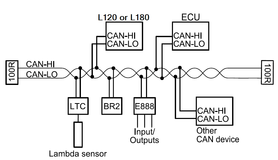
The L180 acquires data from other devices, such as an ECU, for logging and telemetry. It can be used in a wide range of applications as a standalone logger, or intergrated with other electronic devices such as displays and PDMs.

FEATURES

  • Suitable for bikes, cars, marine and industrial applications
  • Optional USB logging (includes 500 MB Internal Logging)
  • Supports T2 Telemetry (Optional)
  • Supports Wideband Lambda from MoTeC PLMs or LTCs
  • GPS Lap Timing
  • Tell Tales
  • Diagnostic Logging
  • Preserved Channels
  • Running Min/Max, Timers, PID Control, Engine Log
  • Easily integrates with MoTeC CAN based devices such as ECUs and expanders

ACCESSORIES

  • 62206 – L180 LOOM
  • 61279 – CABLE USB LOGGING 1.5M (PANEL MOUNT)
  • 61280 –
  • 61292 – 32 GB USB3 FLASH DRIVE
  • 61402 – 32 GB AUTOSPORT USB DATA PLUG
  • 61403 – CABLE, AUTOSPORT USB LOGGING 1.5M (PANEL MOUNT)

OPTIONAL UPGRADES

  • 29702 – L180 44 I/O (see Specifications and Pinout)
    • 10 extra analogue voltage inputs (AV11 to AV20)
    • 4 extra analogue temperature inputs (AT5 to AT8)
  • 29715 – L180 500MB LOGGING + USB
  • 29721 – L180 PRO ANALYSIS
  • 29724 – L180 T2 TELEMETRY
  • 29706 – L180 ADVANCED FUNCTIONS
    • Advanced Maths
    • Channel Maths
    • 16 x 2D Tables (instead of 4)
    • 16 x 3D Tables (instead of 4)
    • 50 User conditions (instead of 20)

SPECIFICATIONS

Logging
  • 250 MB internal logging memory
  • Optional USB logging to a removable storage device
    • Includes upgrade to 500MB internal memory
  • Logging rates up to 1000 samples per second
  • Fast Ethernet download
  • i2 Standard data analysis software included (Pro Analysis upgrade available)
Removable USB Storage Device Options
  • Kingston 32 GB USB3 Flash Drive - fast, low weight and low cost, not mechanically latched or waterproof.
  • MoTeC 32 GB USB3 Data Plug - mechanically latched, waterproof with anodised housing, ideal for exposure to the elements and vibration.
Alternative USB storage devices may be used but are not recommended.
Inputs
(*Denotes number available with I/O upgrade)
  • 10 (20*) analogue voltage inputs:
    • 4 (8*) 0 to 5.46 V, 1.33 mV resolution
    • 6 (12*) x 0 to 15.0 V, 3.66 mV resolution
  • 4 (8*) Analogue temperature inputs
    • 0 to 15.0 V, 3.66 mV resolution
  • 4 x Digital inputs
  • 2 x Switch inputs
  • 4 x Speed inputs
Outputs
  • 6 x low side outputs PWM or switched operation
  • 1.0 Amp max, current limited and thermal overload protected
Expanders
  • Compatible with E816, E888, VIM and SVIM Expanders.
Internal Sensors
  • 3-axis accelerometer, detection range: +/- 5G
  • Dash temperature sensor
  • Sensor supply voltage
  • Battery voltage
Communications
  • 4 x configurable CAN buses, with individually programmable CAN bus speeds. One can be used as RS232 Receive. Two buses support VIM/SVIM Expanders.
  • 2 x Dedicated RS232 ports.
Power supply
  • Operating voltage: 6 to 32 V DC
  • Operating current: 0.4 A typical at 14 V (excl. sensor currents)
  • Reverse battery protection
  • Battery transient protection
Sensor supply currents
  • 5 V sensor supply: 0.25 A maximum
  • 8 V sensor supply: 0.25 A maximum
Operating temperature
  • Internal: -20 °C to 80 °C
  • Typical ambient temperature range in free air: -20 °C to 65 °C
Physical
  • Size: 134.5 x 103.9 x 20.2 mm excluding connectors
  • Weight 350g
  • 1 x 79 pin Autosport connector
  • 1 x mini USB port (type B)
  • The device is rated to IP67

    IP rating is dependant upon the user ensuring that the connector entries are waterproof, which, as a minimum, requires all unused wire cavities on the connector to be plugged.

COMPATIBILITY

  • MoTeC ECUs: All models (some earlier models may require an additional adaptor in conjunction with the RS232 adaptor)
  • MoTeC Displays/Loggers: All
  • MoTeC Expanders: E816 and, E888 , VIM and SVIM expanders.
  • MoTeC Accessories: SLM, PLM, LTC, BR2, PDM, GPS, ADR2, V2 etc.
  • Many non-MoTeC devices

SOFTWARE

  • Microsoft Windows based software
  • Used for setup and management of the data logging system, providing:
    • Configuration of the inputs, ouputs, data logging and calculations.
    • Offline generation of a configuration file that can then be sent to the device.
    • Channel monitoring
    • Firmware updating and extensive help screens
  • i2 Data Analysis software provides the tools for comprehensive data analysis. Standard or Pro* version available
  • T2 Telemetry* software

(* available via upgrades)

ETHERNET WIRING

This pinout is suitable for cables identified as Revision: A and Revision: B on the affixed label.Note: Check the revision of the cable (identified on the label) before using the relevant pinout information from the table.

RJ45 M170/M182/M190 L180/C185/C187/C1812
Pin Function Revision MoTeC Colour Pin Numbering M170 Pin M182/M190 Pin Function L180/C185/ C187/C1812 Pin Function
1 Ethernet TX+ Rev A & Rev B Orange-White 55 C33 Ethernet RX+ 77 Ethernet RX+
2 Ethernet TX– Rev A & Rev B Orange 61 C26 Ethernet RX– 78 Ethernet RX–
3 Ethernet RX+ Rev A Green-White 48 C41 Ethernet TX+ 67 Ethernet TX+
Rev B Green
6 Ethernet RX– Rev A Green 47 C34 Ethernet TX– 68 Ethernet TX–
Rev B Green-White

ECU WIRING

When using an M4, M48 or M8 ECU, the L180 should be connected via RS232. For some ECUs, a PCI cable may also be required.

The Display Logger should be connected via the CAN bus when using an M1 or ‘hundred series’ ECU(M400/M600/M800/M880) or M84, and any number of other CAN devices. Example:

Detailed wiring information is available in the help topics of the C185 Dash Manager software at https://www.motec.com.au/downloads

DIMENSIONS AND MOUNTING

Measurements in mm.

Note: Do not remove any part of the casing. The case provides electromagnetic screening to avoid interference with other equipment, and is also essential for thermal management. Thermal management may be compromised if mounted in a confined space, refer to the operating temperature specifications. Ensure product is not stressed when mounted.

PINOUT

Mating Connector: Part number 68086

Pin Name Standard Function
1 AV15 Analogue Voltage Input 15 (with 44 I/O upgrade)
2 AV16 Analogue Voltage Input 16 (with 44 I/O upgrade)
3 AV17 Analogue Voltage Input 17 (with 44 I/O upgrade)
4 AV18 Analogue Voltage Input 18 (with 44 I/O upgrade)
5 AV19 Analogue Voltage Input 19 (with 44 I/O upgrade)
6 0V Sensor 0 V
7 BAT- Battery Negative
8 BAT+ Battery Positive
9 AUX1 Auxiliary Output 1
10 AUX2 Auxiliary Output 2
11 AUX3 Auxiliary Output 3
12 AUX4 Auxiliary Output 4
13 AUX5 Auxiliary Output 5
14 AUX6 Auxiliary Output 6
15 RS232-2 TX RS232-2 Transmit Output
16 RS232-2 RX RS232-2 Receive Input
17 0V Sensor 0 V
18 5V Sensor 5 V
19 AV7 Analogue Voltage Input 7
20 AV8 Analogue Voltage Input 8
21 AV9 Analogue Voltage Input 9
22 AV10 Analogue Voltage Input 10
23 AV11 Analogue Voltage Input 11 (with 44 I/O upgrade)
24 AV12 Analogue Voltage Input 12 (with 44 I/O upgrade)
25 AV13 Analogue Voltage Input 13 (with 44 I/O upgrade)
26 AV14 Analogue Voltage Input 14 (with 44 I/O upgrade)
27 0V Sensor 0 V
28 5V Sensor 5 V
29 Reserved
30 Reserved
31 Reserved
32 Reserved
33 0V Sensor 0 V
34 AT1 Analogue Temp Input 1
35 AT2 Analogue Temp Input 2
36 AT3 Analogue Temp Input 3
37 AT4 Analogue Temp Input 4
38 AT5 Analogue Temp Input 5 (with 44 I/O upgrade)
39 AT6 Analogue Temp Input 6 (with 44 I/O upgrade)
40 0V Sensor 0 V
41 AT7 Analogue Temp Input 7 (with 44 I/O upgrade)
42 AT8 Analogue Temp Input 8 (with 44 I/O upgrade)
43 0V Sensor 0 V
44 5V Sensor 5 V
45 AV1 Analogue Voltage Input 1
46 AV2 Analogue Voltage Input 2
47 AV3 Analogue Voltage Input 3
48 AV4 Analogue Voltage Input 4
49 AV5 Analogue Voltage Input 5
50 AV6 Analogue Voltage Input 6
51 0V Sensor 0 V
52 DIG1 Digital Input 1
53 DIG2 Digital Input 2
54 DIG3 Digital Input 3
55 DIG4 Digital Input 4
56 0V Sensor 0 V
57 SW1 Switch Input 1
58 SW2 Switch Input 2
59 CAN4L CAN 4 Low
60 CAN4H CAN 4 High
61 0V Sensor 0 V
62 8V Sensor 8 V
63 SPD1 Speed Input 1
64 SPD2 Speed Input 2
65 SPD3 Speed Input 3
66 SPD4 Speed Input 4
67 E-TX+ Ethernet Transmit +
68 E-TX- Ethernet Transmit -
69 AV20 Analogue Voltage Input 20 (with 44 I/O upgrade)
70 RS232-1 TX RS232 Transmit Output
71 CAN3L CAN 3 Low
72 CAN3H CAN 3 High
73 CAN1L CAN 1 Low
74 CAN1H CAN 1 High
75 CAN2L CAN 2 Low / RS232 Ground Input
76 CAN2H CAN 2 High / RS232 Receive Input
77 E-RX+ Ethernet Receive +
78 E-RX- Ethernet Receive -
79 RS232-1 RX RS232 Receive Input

PURCHASING

If you are interested in purchasing this product contact an Authorised MoTeC Dealer.

DOWNLOADS

Useful Links

This page shows the relevant downloads for this product. For a full selection of MoTeCs downloads visit the Downloads page.


To keep up-to-date with the latest webinars or software you can subscribe to our mailing lists and we will send you a message when new items are released.

To sign-up for a mailing list click the "SIGN-UP: WEBINAR NEWS" or "SIGN-UP: SOFTWARE RELEASE" button below.

OVERVIEW

FEATURES

ACCESSORIES

OPTIONAL UPGRADES

SPECIFICATIONS

COMPATIBILITY

SOFTWARE

ETHERNET WIRING

ECU WIRING

DIMENSIONS AND MOUNTING

PINOUT

PURCHASING

DOWNLOADS