The MoTeC Logo
Welcome
Products
Downloads
Training
Forum
FAQ
Careers
Dealers
Products
The MoTeC Logo
Welcome Products Downloads Training Forum FAQ Careers Dealers
The MoTeC Logo
Nissan R35 GT-R 2007 M1 Kit
Part No: #11501 & 11502

OVERVIEW

MoTeC's Nissan R35 GT-R Engine Plug-In ECU Kit is a fully programmable replacement for the factory-fitted engine ECU. No rewiring is necessary; the kit plugs into the stock wiring harness using the original fuel system and sensors (except Lambda sensors).

All Original Equipment (OE) functions are maintained, including dashboard, traction control and gearbox systems.

Every aspect of the ECU's functionality is fully tunable, including additional capabilities far beyond the OE ECU tailored for drag and circuit racing applications.

2019 UPDATE

  • Firmware version 01.05.0078 for M150, version name April 2016.
  • ECU firmware is compatible with all known variants of R35 in all geographic regions, 2007 to current (2019).

    Note: Each variant may have unique tuning settings.

  • Adaptor Box Revision D supports 2017+ models with Exhaust Sound control and Alternator Current sensing.

This update provides extensive feature improvements and adds many new features.

  • Slip-Based Traction Control added
  • Traction Model system added
  • Flex Fuel and Dual Fuel control added
  • AWD control added
  • Internal TCM data reading added
  • Boost Dual Bank Control added
  • Nitrous control added
  • Boost Servo control added
  • Gear Up shift Torque reduction control added
  • Clutch Slip Control improvements
  • Knock control system improvements
  • Launch system improvements
  • OE CAN Integration tunability improvements
  • Driver map switch additions and improvements
  • Warning system additions and improvements
  • OE VDC (ABS) removal support
  • Bosch Motorsport ABS M4 and M5 support
  • Bosch CAN Inertial sensor support
  • Calculation rates increased to improve control of various subsystems
  • Bug fixes, additions and improvements to many other areas.

For more details on new and existing features, see the Feature Details section.

For details on migrating an existing tune from an older version to this release, see the Migration Checklist.

KIT CONTENTS (11501 - 11502)

Hardware
  • 13150 – M150 ECU preloaded with the Nissan GT-R 2007 VR38DETT Engine M1 Package. (A MoTeC M1 Licence is required to run this Package.)
  • 61245 – M150 NISSAN GTR R35 RHD ADAPTOR KIT– containing:
    • 61248 – M150 NISSAN GTR R35 ADAPTOR BOX
    • 61247 – M150 NISSAN GTR R35 BREAKOUT LOOM
    • 61250 – M1 ADAPTOR 200MM 34W KEY 2 STUB LOOM
    • 61251 – M1 ADAPTOR 120MM 26W KEY 3 STUB LOOM
    • 61252 – M1 ADAPTOR 120MM 34W KEY 1 STUB LOOM
    • 61253 – M1 ADAPTOR 200MM 26W KEY 1 STUB LOOM
    • 61225 – NETWORK CABLE RJ45 1.5 METRE
    • 61305 – LTCD - DUAL NTK LAMBDA TO CAN
    • 61220 – LAMBDA SENSOR EXTENSION LOOM FOR NTK E1 0.55 METRES x 2
    • 57007 – NTK UEGO WIDEBAND LAMBDA SENSOR x 2
    • 54002 – DELCO AIR TEMPERATURE SENSOR 14 x 1.5mm
    • 3M DUAL LOCK VELCRO 100MM x 3
  • 61249 – M150 NISSAN GTR R35 LHD ADAPTOR KIT– containing:
    • 61248 – M150 NISSAN GTR R35 ADAPTOR BOX
    • 61247 – M150 NISSAN GTR R35 BREAKOUT LOOM
    • 61254 – M1 ADAPTOR 150MM 34W KEY 2 STUB LOOM
    • 61255 – M1 ADAPTOR 150MM 26W KEY 3 STUB LOOM
    • 61256 – M1 ADAPTOR 200MM 34W KEY 1 STUB LOOM
    • 61404 – M1 ADAPTOR 250MM 26W KEY 1 STUB LOOM
    • 61225 – NETWORK CABLE RJ45 1.5 METRE
    • 61305 – LTCD - DUAL NTK LAMBDA TO CAN
    • 61220 – LAMBDA SENSOR EXTENSION LOOM FOR NTK E1 0.55 METRES x 2
    • 57007 – NTK UEGO WIDEBAND LAMBDA SENSOR x 2
    • 54002 – DELCO AIR TEMPERATURE SENSOR 14 x 1.5mm
    • 3M DUAL LOCK VELCRO 100MM x 3
Licence
  • 23002 – NISSAN R35 GT-R

This Licence is required to run the Nissan GT-R 2007 VR38DETT Engine M1 Package in the M150 ECU.

FEATURE DETAILS

  • M150 ECU hardware
    • 40 outputs
    • 45 inputs
    • 3 x CAN, RS232, LIN, Ethernet.
  • Traction control
    • Controls front to rear wheel slip closed loop to an aim value.
    • Torque reduction by ignition timing or cut for fast response.
    • Tunable and dynamically adjustable aim slip.
  • Traction Model system
    • Controls the maximum wheel torque via throttle reduction.
    • Dynamically adjustable for lateral and vertical G force and downforce.
    • This open loop system works in conjunction with the closed loop slip based control.
  • Flex Fuel and Dual Fuel control
    • Model based fuel type selection, reduces tuning time.
    • Comprehensive tunability.
    • Ethanol sensor support.
  • AWD control
    • Replaces the OE AWD control unit.
    • Controls torque to the front wheel.
    • Open loop and closed loop control based on driving conditions.
    • Allows 2WD mode (gearbox hardware dependant).
  • Internal TCM data
    • Reading and logging of over 50 Internal TCM channels.
    • Includes clutch pressure actual and commanded, rest and touch points, selector positions, axis pressures, etc.
    • Very useful for transmission tuning and fault finding.
  • Boost dual control
    • Two separate closed loop control systems with respective boost control solenoid outputs and boost pressure sensors.
    • Comprehensive tuning including influences for Barometric pressure and Gear.
    • Allows cross-flow intercoolers to be used on the GT-R while maintaining bank to bank boost-pressure balance.
    • Integrates with Torque Control System; torque control by boost control option.
  • Nitrous control
    • For wet or dry nitrous oxide systems.
    • Two stage with multiple trigger conditions and time limits.
    • Nitrous transport delay for dry systems.
    • Fuel pump trigger.
  • Boost Servo control
    • Controls a servo operated wastegate or blow-off valve.
    • Multiple sources for aim position.
    • Use for boost control, blow-off valve or turbo surge prevention.
  • Gear Up shift Torque reduction
    • Fully tunable gear shift torque reduction amount based on current torque and clutch slip.
    • Ignition retard and/or ignition/fuel cut methods.
    • Integrates with TCM based torque reduction control.
  • Clutch Slip Control
    • Reduce torque by throttle control to protect the clutch from damage (overheat).
    • Reduce torque (by ignition retard) closed loop to an aim slip, which maximises performance from the clutch.
  • Knock control system
    • Engine Knock detected by DSP to filter out noise.
    • Individual cylinder control, only acts on cylinder that is knocking.
    • Controls knock for excessive events by:
      • Reducing ignition timing
      • Adding fuel or ignition cut
    • Control filtering based on single event, transient conditions or gear shift.
  • Launch control
    • Closed loop engine speed control using ignition timing and cut.
    • Builds boost without loading the engine, giving very consistent engine speed and torque available for takeoff.
    • Fast boost building using higher engine speed, reducing to desired launch engine speed as boost rises to the requested.
    • 'Bump in' functionality specific for GT-R.
  • Driver map switch
    • Multiple toggle, latching or 10 position switch inputs.
    • Link switches to one or multiple subsystem controls.
    • Map switching and/or enable control for useful subsystems, e.g. Throttle Pedal, Traction Control, Gear shift, Anti Lag.
  • Warning system
    • Light output and Check Engine Lamp.
    • Solid or flashing at 0.5Hz, 1Hz or 5Hz depending on severity of the warning.
    • Threshold limits with time delays all configurable.
    • Warnings for diagnostic conditions and subsystem active.
  • Comprehensive OE systems integration
    • Rescale Boost gauge reading on MFD for high boost.
    • Show Ethanol content sensor on the dash.
    • Steering wheel map switching display on the dash.
  • OE TCM (DSG transmission) integration
    • Obeys commands from the TCM as per OE.
    • Down shift Throttle Blip with rev matching.
    • Up shift torque reduction by ignition retard.
    • Torque limit for shift blending and transmission limp home.
    • Tunable for takeoff, shift feel, shift points, launch and more.
  • OE VDC (ABS) integration
    • VDC system operates as per OE.
    • Obeys torque reduction commands for traction control, ESP and Limp home (tunable).
    • Supports removal of the VDC and other OE systems will still operate as normal.
  • Bosch Motorsport ABS M4 and M5 support
    • This can replace the OE VDC unit.
  • Bosch CAN Inertial sensor MM5.10 support
  • Torque modelling
    • Based on normal engine tuning, e.g. the tuning process is no more difficult or time consuming than tuning an M1 ECU without torque modelling.
    • Limit torque accurately, compensates for any boost pressure.
    • Integrates with ignition timing and ignition/fuel cut systems for seamless blending between torque reduction methods.
  • Engine Load (fuelling) calculation from different sources
    • Inlet Manifold Pressure sensors.
    • Mass Air Flow sensors.
    • Throttle Position and Boost Pressure.
    • Combination of the above.
  • Cruise Control
    • Functionality exactly like the OE ECU.
    • Set speed adjustable in 1 and 5 kmh or mph increments.
    • Fully tunable control.
  • Fuel Closed Loop mixture control for individual banks.
  • Driver Steering Wheel map switching
    • Displays setting on the OE dash.
    • Up/down buttons for 10 positions
    • Cancel button (momentary or toggle) for 2 positions.
  • Integrated 250 Mbyte of logging memory.
  • Includes Level 2 Data Logging
    • 200 channels at up to 200Hz.
    • Upgradable to 2000 channels at up to 1000Hz.
  • Data analysis via MoTeC's renowned i2 software.
  • Control for 3 separate fuel pumps
    • OE multi speed pump control.
    • Sub fuel pump control.
    • PWM closed loop fuel pressure control system.
    • Options for many fuel pump and system configurations.
  • Fallback and limp home strategies
    • If a sensor fails (e.g. MAP), alternate load sensors are used.
  • Easy wiring of additional sensors via the 'breakout' connector: multiple EGTs (via TCA Thermocouple Amplifier or up to 8 via E888), GPS.
  • Gear Automatic shift control, allows fully tunable gear shift points.
  • Injector outputs for 12 individual injectors
    • Peak and Hold or Saturated drive types for all outputs
    • Tunable Balance table, injection timing,
    • Comprehensive blending and transport delay compensations for secondary (high) injectors.
  • Ignition output pin for each cylinder (coil on plug).
  • Camshaft timing control
  • Dual bank lambda sensor control with LTCD module supplied with the kit.
  • Engine Physical settings for fast setup and minor re-tuning for many modifications.
  • Engine pumping efficiency, air flow and load modelling based on inlet manifold pressure.
  • Dual bank fuelling
    • Each bank can be fuelled from its respective set of sensors, MAF, Boost, MAP, TP, AT.
    • Redundant sensor support; if one sensor fails the other bank's sensor is automatically substituted.
  • Sensor calibrations available for many common automotive sensors.
  • Transient fuelling compensation using physical modelling of fuel film remaining in the inlet manifold.
  • Support of MoTeC devices: ADR, E8XX, PDM, SLM, VCS.
  • Test settings for most outputs, including injection and ignition outputs, for easier setup.
  • Wastegate Pressure closed loop control, e.g. for CO2 systems.
  • Anti Lag system
    • Controls ignition timing, fuel volume, ignition cut, engine speed limit, boost aim and torque (opens throttle).
    • Setup for circuit, rally or roll racing (rolling launch).
  • Turbocharger bypass valve control (electric blow-off valve).
  • Coolant fan outputs
    • Controls OE fans.
    • Additional PWM or switched control.
    • Integrated with air conditioner and idle control.
  • Air Conditioner control
    • Conditional clutch activation
    • Refrigerant pressure safety
    • Fan control
  • Coolant Temperature compensations for engine speed limit, ignition timing, fuel mixture and boost limit.
  • Coolant Pump output with PWM control.
  • Coolant Pump After Run functionality, optionally with additional pump output.
  • Engine Speed Limiting with ignition cut and/or fuel cut.
  • Fuel Flow Supply and Fuel Flow Return sensor inputs.
  • Exhaust Sound control for MY17+ models.
  • Charcoal canister purge valve control.
  • GPS data via CAN or RS232.
  • Intercooler Temperature and spray control.
  • Differential oil temperature control with dedicated temperature sensor and pump output.
  • Engine Charge air temperature calculation, allows for correction of Inlet Air Temperature (compensation of heat soak effect etc.).
  • Lap distance, time and number via BR2, GPS or switched input, with split and sector options.
  • Race Time system
    • Trim tables for ignition timing, fuel mixture, boost limit and torque limit.
    • Integrates with launch and traction control
  • Idle control system using ignition timing and throttle control.
  • Engine Load Average, allows trims to be applied with persistent high engine load.
  • Dedicated fuel, ignition and throttle setting for cranking and post start.
  • Closed loop Alternator control
  • Engine hours, odometer and trip meter.
  • Configurable security for multiple users.
  • Configuration of Brake State using a switch or a pressure sensor.
  • Brake Vacuum system with pump control.
  • ECU-internal G-force (acceleration) – longitudinal, lateral and vertical.
  • ECU CAN receive from a defined CAN ID for data reception from MoTeC devices. Support of 3 CAN buses.
  • ECU CAN transmit of the most common channels using standard MoTeC CAN templates, ideal for MoTeC dash displays.
  • Tachometer output.
  • Dual bank Drive by Wire Throttle Servo control.
  • Throttle Pedal sensor with translation table.
  • Transmission Pump output with transmission temperature threshold and hysteresis control.
  • Vehicle Speed measurement using wheel speed sensors, estimation or GPS.
  • Vehicle Speed Limit Control system (DBW-throttle based). Can also be used for pit speed limiting.
  • Auxiliary Time system with tables for ignition timing compensation, fuel volume trim and fuel mixture aim.
  • 5 Auxiliary Outputs for PWM control of added actuators:
    • Duty cycle tables using Engine Speed and Throttle or Manifold Pressure Axis.
    • Activation based on inlet manifold pressure or throttle position.
    • Auxiliary Output 1 includes tables for Ignition Timing Compensation, Fuel Volume Trim and Fuel Mixture Aim.
    • Auxiliary Output 5 includes external sensor input.
  • Optional channels for additional sensors via input pin and/or CAN message, including:
    • Airbox Mass Flow, Pressure and Temperature
    • Ambient Temperature
    • Brake Pressure Front and Rear
    • Brake Switch
    • Coolant Pressure and Temperature
    • Engine Oil Pressure and Temperature
    • Engine Crankcase Pressure
    • Exhaust Pressure Bank 1 and Bank 2
    • Exhaust Temperature (EGT) via TCA Thermocouple Amplifier, Generic CAN, or E888 for Bank 1 and 2 Collector, and Cylinders 1 to 6.
    • Exhaust Lambda via LTC, LTCN, or PLM for Bank 1 and 2 Collector, and Cylinders 1 to 6.
    • Fuel Pressure and Temperature
    • Fuel Tank Level
    • Gear Neutral Switch
    • Gear Shift Request
    • Intercooler Temperature
    • Steering Angle and Pressure
    • Transmission Pressure and Temperature
    • Turbocharger Speed
    • Turbocharger Inlet/Outlet Temperature
    • Turbocharger Wastegate Position
    • G-Force (Acceleration) – Longitudinal, Lateral, Vertical.
    • Wheel Speed sensors front/rear left/right, wired or CAN input.
    • Auxiliary Fuel Pressure

MODIFICATIONS GUIDE

While many components may be changed to achieve better performance, some combinations are more likely to deliver improvements with minimal re-tuning from the installer, tuner, or customer.

In general, Original Equipment (OE) or stock fuel injection components are suitable for improved performance. However, when the capabilities of certain OE fuel injection components reach their limits (for example, inadequate injector flow), it is necessary to replace these components with higher performance alternatives.

MoTeC has conducted many tests to characterise components for optimal performance within the M1 environment. This is particularly relevant in regard to our comprehensive, precise and highly repeatable injection calibration testing, which allows for fuel pressure and supply voltage variations. Each injector for which we supply data has been subject to some 400 tests; this level of detail is not likely to be achieved by installers, tuners or customers.

It is our recommendation that components are chosen from our list of suitable options when selecting alternate parts.

Each component listed below includes the settings which should be adjusted or checked with M1 Tune. Clicking on these settings within M1 Tune displays operational help relevant to the item.

COMPONENT MODIFICATION GUIDE
Flex Fuel and Dual Fuel

When adding Flex Fuel (variable ratio of gasoline and ethanol) or Dual Fuel (separate fuels on primary and secondary injectors) to the engine, see the M1 Flex Fuel User Guide available on the MoTeC website.

Fuel Type

The fuel type can be changed to one of a different chemistry (provided the fuel is compatible with spark ignition engines), like ethanol or methanol. Changing the Fuel Properties setting for the new fuel will adjust the fuel delivery to give close to the correct fuel mixture.

Other aspects of changing the fuel type may require re-tuning to take advantage of a better quality fuel, or for engine safety. For example, ignition timing, fuel film, boost aim and knock control might be some of the systems that require re-tuning.

Fuel Injectors

When changing the injectors, the settings under the 'Fuel Injector' group must be adjusted to reflect such a change.

If accurate injector calibrations are used, only minor re-tuning may be necessary.
Primary/Secondary Injectors

If a secondary set of injectors is fitted higher in the inlet manifold runner, the following setting groups require setup and tuning:

  • Fuel Injector Secondary
  • Fuel Cylinder N Secondary Output Resource
  • Fuel Timing Secondary
  • Fuel Film Secondary

Additional wiring is required to run from the ECU to the engine bay carrying ECU 12V power and 6x Peak Hold injector outputs.

Turbo and Wastegate

Any suitable turbo and wastegate combination may be used. Settings in the Boost group will need adjusting. Depending on the wastegate type, Boost Servo or Wastegate groups may also need adjusting.

Throttle Bodies

Any throttle body with direct actuation of the DC servo can be used, including those with digital SENT throttle position sensors. The following setting groups must be tuned:

  • Throttle Servo - If your new throttle part number is not in the 'Throttle Servo Calibration' list, please contact MoTeC for advice.
  • Throttle Mass Flow Area Factor - This parameter sets the maximum airflow factor of the throttle. It may be scaled by the change in throttle area from old throttle to new. For example, if increasing from 60mm to 70mm throttles, the Throttle Mass Flow Area Factor would be multiplied by 1.361.
  • Throttle Area - This table sets the relationship between throttle position and throttle opening area. This is tuned by matching Inlet Manifold Pressure Bank N Sensor to Inlet Manifold Pressure Modelled. For low throttle opening and especially near idle, accuracy of this table is important, but also easy to tune. At higher throttle openings tuning becomes more difficult, but also much less important. Provided the shape of the table from the base tune is maintained, accurate torque control can be obtained for all throttle openings in a short time.
Fuel Pumps

There are many aftermarket fuel pump kits available for the GT-R. The M1 Package has flexible configuration to allow switched, staged PWM or closed loop PWM control of 3 separate fuel pumps. An external driver module such as MoTeC Dual Half Bridge (DHB) may be used for high current PWM control.

Please see the Package help in the following groups:

  • Fuel Pump
  • Fuel Pressure Control
Inlet Manifold and Plenum Chamber

If the OE inlet manifold is changed, this can have a small effect on the Torque Control System. The following settings should be adjusted:

  • Inlet Manifold Volume, set to the new manifold volume.
  • Inlet Manifold Pumping Gain, set by testing the response of a changing torque limit.
  • A change in the manifold will also likely change the engine's pumping efficiency so re-tuning of fuel and ignition should be carried out.
Intercooler

Previously, fitting a cross-flow type intercooler meant the boost pressure could become unbalanced from bank to bank as there is only a single boost control valve for both turbos. Now, if a cross-flow intercooler is fitted, it is recommended to also fit a second boost control solenoid so that the ECU has control over both turbos independently. The second boost control is set up in Boost Control Bank 2. It is also recommended to fit a second inlet manifold pressure sensor so that each bank is fuelled from its own sensor.

MAF (Mass Air Flow) Sensor
OE MAF sensors may be removed. While their signal can be used for fuelling, it is not a necessity.

The standard MAF sensor provides an adequate measurement range up to 650HP (480kW). If the standard sensor is placed in a larger diameter housing it is necessary to adjust the sensor calibration. An approximate calibration can be achieved by using the squared ratio of cross-sectional areas of the original housing and the replacement housing.

For example:

Standard housing is 64mm, new housing may be 80mm.

Ratio would be (80/64)^2 = 1.5625

Squared Ratio would be 1.5625 (that is, 56% more flow at a given voltage reading).

For best accuracy, the sensor can be physically calibrated against a flow bench or reference sensor.

Boost and MAP Sensors

The OE boost sensor has a range to 270kPa absolute which equates to 1.7 bar or 25lbs of boost. If higher boost levels are required, the boost sensor must be replaced with another that has a higher range. Boost sensors must be absolute or sealed gauge type sensors. Gauge sensors are not supported, but the sensors do not need to read below ambient pressure (vacuum).

The OE MAP sensor must also be changed to cover the full range of boost down to high vacuum. If a second MAP sensor is fitted to the other bank plenum, the ECU will fuel each bank from its respective sensor. This has the advantage of correctly fuelling both the banks in case of a turbo or boost control issue causing unbalanced boost pressures.

Respective sensor settings must be updated to suit the new sensor.

AWD control

The Transfer of torque to the front wheels is achieved by energising the AWD solenoid inside the transmission. The GT-R has a control module dedicated to this solenoid, solely reading information from the CAN bus to calculate the amount of front wheel torque required at any given time.

The M1 ECU can replace the front wheel torque transfer functionality by removing the AWD control module located beneath the front right hand seat and extending the wiring for the solenoid (two wires) to the GT-R Adaptor Box 'E' Connector, pins 17 and 18.

AWD control is then fully tunable from within the ECU and can be switched off for 2WD mode (depending on the AWD clutch assembly). The ECU then also controls the AWD dash warning lamp. See the Transfer group in the Package.

ECU Gear shifting

Gear shifts can be triggered by the ECU based on Engine Speed, Throttle Position and Driver switch setting allowing fully automatic gear shifting (up and down) for circuit or drag racing and street driving.

The ECU is wired to the shift paddles to trigger the gear shifts. Wire from spare low side ECU outputs (recommend Ign LS 11,pin A08 and Ign LS 12, pin A09) to the OE connector located near the ECU as shown below from the Nissan GT-R workshop manual.
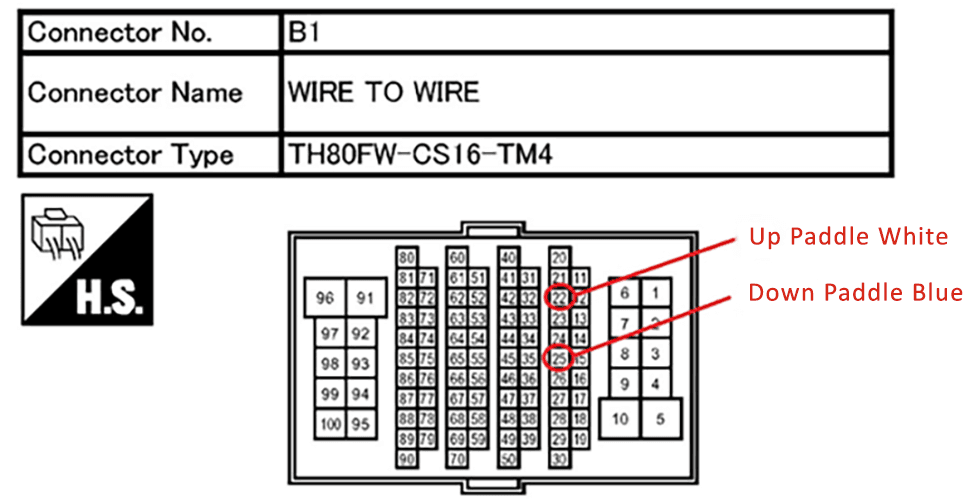
To set up gear shifting, see Gear Request, Gear Automatic and Gear Shift groups in the Package.

MIGRATION CHECKLIST

The April 2016 (v1.05.0078) Package differs dramatically from the previous release (May 2015 v01.04.0005). It uses the newer M1 system version 1.4, which allows greater flexibility in selecting resources and hiding unused features from the Tune interface.

If upgrading the Package, the tuning values for fuel, ignition, sensor/injector calibrations and the like remain the same so the car should not need to be re-tuned on a dyno. However, the fuel mixture and timing values should be checked after the upgrade process is complete.

It is MoTeC's strong recommendation that current users of this product download the new Package from MoTeC Online and migrate only those settings from their existing Packages that are unique for their vehicle, such as Engine Efficiency, Ignition Timing and Boost Aim.

Below is a list of the more important objects that should and shouldn't be migrated from an existing tune from a previous version. This is not a comprehensive list; settings or setting groups that are not mentioned specifically should be compared from version to version using the 'Compare Firmware' tool. Read the help detail for both and decide if the tuning for the object should be migrated, re-tuned or the base setting kept.

Many new settings and subsystems have been added that can be explored.

Settings that may be migrated directly:

  • Anti Lag group (except Anti Lag Ignition Timing table)
  • Brake Switch settings
  • Coolant Temperature tables
  • Cruise subsystem
  • E8XX settings
  • Engine Efficiency table
  • Engine Load Average group
  • Engine Speed group
  • Engine Overrun group
  • Fuel Mixture group
  • Fuel Film group
  • Fuel Pressure Control group (except Fuel Pressure Control Aim/Pump)
  • Fuel Injector Primary/Secondary groups. Note: settings have been added.
  • Fuel Purge group
  • Fuel Pump group (except Fuel Pressure Control Pump)
  • Fuel Closed Loop group
  • Gear group
  • GTR group (except for items that moved to generic subsystems, GTR Air Conditioner and GTR Coolant Fan).
  • Idle group (except Idle Ignition Timing group).
  • Ignition group (except Ignition Coil group)
  • Inlet Manifold group (except Inlet Manifold Temperature group).
  • Inlet Camshaft group. Note: some parameters have changed to tables.
  • Launch group (except Launch Ignition Timing).
  • Throttle group. Note: there are some differences and settings should be checked after migrating all.
  • Torque group (except Torque Ideal Generated and Torque Ideal Correction).
  • Vehicle Speed group

Settings that can be migrated but object names have changed:

  • All Sensor Calibration tables have changed to Sensor Translation. The Sensor Calibration name is now used to select specific sensor parts.
  • Anti Lag Ignition Timing Limit Advance has changed to Anti Lag Ignition Timing.
  • Boost Control group has changed to Boost Control Bank 1.
  • Engine Charge Cooling group, parameters changed to tables.
  • Exhaust Lambda Bank/Cylinder N Mode has changed to Exhaust Lambda Bank/Cylinder N CAN Bus.
  • Fuel Molar Mass/Stoichiometric Ratio/Density setting has changed to the Fuel Properties group.
  • Fuel Volume Cylinder N groups has been combined with Fuel Cylinder N groups.
  • Fuel Timing Primary/Secondary tables has changed to Fuel Timing Primary/Secondary Main.
  • Fuel Pressure Aim has changed to Fuel Pressure Control Aim.
  • Fuel Pressure Pump External has changed to Fuel Pressure Control Pump.
  • Inlet Manifold Temperature group has changed to Inlet Air Temperature. Note: Inlet Manifold Temperature now refers to the temperature of the manifold itself.
  • Idle Ignition Timing Limit Advance group changed to Idle Ignition Timing.
  • Ignition Charge group has changed to Ignition Coil Charge group.
  • Torque Ideal Frictional Loss has changed to Torque Ideal Correction Internal Loss.

For subsystems that have changed substantially, the base file settings should be kept, but can be re-tuned for non standard installations.

  • Air Conditioner subsystem
  • All Sensor CAN has been changed so the CAN resource is now selected in the Sensor Resource.
  • CAN group settings
  • Clutch Slip subsystem
  • Coolant Fan 1, now integrated with Air Conditioner.
  • For all Driver switch settings, the items preset in the base file must be kept. Driver switches from a previous Package can be reassigned to empty positions.
  • ECU group
  • Engine Run Switch group
  • Engine Oil group
  • Knock group has undergone a major upgrade, so some re-tuning is required. Frequencies and Knock Threshold table may be carried over.
  • Launch Ignition Timing Limit Advance has changed to use the Ignition Timing Control system, requires some re-tuning.
  • Torque Ideal Generated table has been replaced with Torque Ideal Generated Scale parameter. A scale of 12mg is equal to an Engine load of 4000mg = Torque of 8000Nm.
  • Warning system, while most objects will migrate, the system has some major improvements which can be reviewed.
  • Wheel Speed group, retain the base settings unless the OE VDC unit has been removed.

PINOUT

M150 Connector A - 34 Way
Mating Connector: Tyco Superseal 34 Position Keying 2 (MoTeC #65067)
Pin Number Designation Full Name OE Pin Function
A01 AT5 Analogue Temperature Input 5 102 Steering Wheel Button
A02 AT6 Analogue Temperature Input 6 E16 Inlet Manifold Temperature Bank 2
A03 AV15 Analogue Voltage Input 15 78 Ambient Pressure
A04 AV16 Analogue Voltage Input 16 E09 Spare to Breakout Plug
A05 AV17 Analogue Voltage Input 17 E15 Fuel Pressure
A06 IGN_LS9 Low Side Ignition 9 TP19 Not Externally Available
A07 IGN_LS10 Low Side Ignition 10 TP20 Not Externally Available
A08 IGN_LS11 Low Side Ignition 11 TP21 Not Externally Available
A09 IGN_LS12 Low Side Ignition 12 Not Used Not Externally Available
A10 SEN_5V0_C1 Sensor 5.0V C Sensor Supply Analogue
A11 LA_NB1 Lambda Narrow Input 1 Internal Front Drive Clutch current sense
A12 LA_NB2 Lambda Narrow Input 2 E10 (Rev all), 35 (Rev E) Battery Current Sensor (MY12+ models)
A13 KNOCK3 Knock Input 3 E21 Spare to Breakout Plug
A14 KNOCK4 Knock Input 4 E13 Spare to Breakout Plug
A15 DIG2 Digital Input 2 E20 Spare to Breakout Plug
A16 DIG3 Digital Input 3 E33 Spare to Breakout Plug
A17 DIG4 Digital Input 4 E34 Spare to Breakout Plug
A18 SEN_5V0_C2 Sensor 5.0V C E29, E30, E31 Sensor Supply Analogue
A19 SEN_5V0_B2 Sensor 5.0V B 87, 88, 91,92, 90 (Rev E) Sensor Supply Rotation
A20 LIN LIN Bus TP23 Not Externally Available
A21 RS232_RX RS232 Receive E22 GPS Receive
A22 RS232_TX RS232 Transmit E23 Telemetry Transmit
A23 DIG1 Digital Input 1 E12 Spare to Breakout Plug
A24 BAT_NEG3 Battery Negative 6,54,124,128,E01,E02,E11 Power Ground
A25 BAT_NEG4 Battery Negative 6,54,124,128,E01,E02,E11 Power Ground
A26 SEN_0V_C1 Sensor 0V C 71 Sensor Zero Volts Analogue
A27 SEN_0V_C2 Sensor 0V C E05, E06, E07, E08 Sensor Zero Volts Analogue
A28 CAN3_HI CAN Bus 3 High Not Used Not Externally Available
A29 CAN3_LO CAN Bus 3 Low Not Used Not Externally Available
A30 CAN2_HI CAN Bus 2 High E04 1M CAN to LTC
A31 CAN2_LO CAN Bus 2 Low E03 1M CAN to LTC
A32 BAT_NEG5 Battery Negative 6,54,124,128,E01,E02,E11 Power Ground
A33 SEN_0V_B1 Sensor 0V B 20 Sensor Zero Volts Analogue
A34 SEN_0V_A1 Sensor 0V A 15,19,22,26 Sensor Zero Volts Analogue
M150 Connector B - 26 Way
Mating Connector: Tyco Superseal 26 Position Keying 3 (MoTeC #65068)
Pin Number Designation Full Name OE Pin Function
B01 OUT_HB9 Half Bridge Output 9 Not Used Not Externally Available
B02 OUT_HB10 Half Bridge Output 10 Not Used Not Externally Available
B03 UDIG8 Universal Digital Input 8 30 Fuel Pump Control Check
B04 UDIG9 Universal Digital Input 9 93 Sub Fuel Pump +
B05 UDIG10 Universal Digital Input 10 94 Sub Fuel Pump -
B06 UDIG11 Universal Digital Input 11 E24 Spare to Breakout Plug
B07 UDIG12 Universal Digital Input 12 E14 Pit switch
B08 INJ_LS5 Low Side Injector 5 8 Evaporative Canister Volume Control Valve
B09 INJ_LS3 Low Side Injector 3 61 Boost Actuator
B10 AV9 Analogue Voltage Input 9 48 Inlet Manifold Pressure Bank 2
B11 AV10 Analogue Voltage Input 10 80 Boost Pressure Bank 2
B12 AV11 Analogue Voltage Input 11 79 Boost Pressure Bank 1
B13 BAT_POS Battery Positive 1,49 Switched Supply
B14 INJ_LS6 Low Side Injector 6 E25 Fuel Pump External
B15 INJ_LS4 Low Side Injector 4 126 Sub Fuel Pump Relay
B16 AV12 Analogue Voltage Input 12 83 Power Steering Pressure
B17 AV13 Analogue Voltage Input 13 89 Air Conditioner Refrigerant Pressure
B18 AV14 Analogue Voltage Input 14 E28 Spare to Breakout Plug
B19 BAT_POS Battery Positive 1,49 Switched Supply
B20 OUT_HB7 Half Bridge Output 7 29 via 5K6 Fuel Pump Main
B21 OUT_HB8 Half Bridge Output 8 Internal Front Drive Clutch control
B22 INJ_PH9 Peak Hold Injector 9 Not Used Not Externally Available
B23 INJ_PH10 Peak Hold Injector 10 Not Used Not Externally Available
B24 INJ_PH11 Peak Hold Injector 11 Not Used Not Externally Available
B25 INJ_PH12 Peak Hold Injector 12 Not Used Not Externally Available
B26 SEN_5V0_A Sensor 5.0V A 95 Sensor Supply Analogue
M150 Connector C - 34 Way
Mating Connector: Tyco Superseal 34 Position Keying 1 (MoTeC #65044)
Pin Number Designation Full Name OE Pin Function
C01 OUT_HB2 Half Bridge Output 2 50 Throttle Servo Bank 2 Motor +
C02 SEN_5V0_A Sensor 5.0V A 84,100 Sensor Supply Analogue
C03 IGN_LS1 Low Side Ignition 1 10 Ignition Cylinder 1 Output
C04 IGN_LS2 Low Side Ignition 2 9 Ignition Cylinder 2 Output
C05 IGN_LS3 Low Side Ignition 3 13 Ignition Cylinder 3 Output
C06 IGN_LS4 Low Side Ignition 4 33 Ignition Cylinder 4 Output
C07 IGN_LS5 Low Side Ignition 5 34 Ignition Cylinder 5 Output
C08 IGN_LS6 Low Side Ignition 6 38 Ignition Cylinder 6 Output
C09 SEN_5V0_B Sensor 5.0V B 96,99 Sensor Supply Analogue
C10 BAT_NEG1 Battery Negative 6,54,124,128 Power Ground
C11 BAT_NEG2 Battery Negative 6,54,124,128 Power Ground
C12 IGN_LS7 Low Side Ignition 7 57 (Rev E) Exhaust Sound Output (Muffler Valve, MY17+)
C13 IGN_LS8 Low Side Ignition 8 113 Tacho out
C14 AV1 Analogue Voltage Input 1 40 Throttle Servo Bank 2 Position Main
C15 AV2 Analogue Voltage Input 2 36 Throttle Servo Bank 2 Position Tracking
C16 AV3 Analogue Voltage Input 3 28 Throttle Servo Bank 1 Position Main
C17 AV4 Analogue Voltage Input 4 32 Throttle Servo Bank 1 Position Tracking
C18 OUT_HB1 Half Bridge Output 1 53 Throttle Servo Bank 2 Motor -
C19 INJ_PH1 Peak Hold Injector 1 25 Fuel Cylinder 1 Output
C20 INJ_PH2 Peak Hold Injector 2 21 Fuel.Cylinder 2.Output
C21 INJ_PH3 Peak Hold Injector 3 17 Fuel Cylinder 3 Output
C22 INJ_PH4 Peak Hold Injector 4 37 Fuel Cylinder 4 Output
C23 INJ_LS1 Low Side Injector 1 116 (Rev E only) Driver Exhaust Sound Switch (input signal, MY17+)
C24 INJ_LS2 Low Side Injector 2 105,127 ECM relay, DBW on/off relay
C25 AV5 Analogue Voltage Input 5 104 Throttle Pedal Main
C26 BAT_POS Battery Positive 1,49 Switched Supply
27 INJ_PH5 Peak Hold Injector 5 41 Fuel Cylinder 5 Output
C28 INJ_PH6 Peak Hold Injector 6 45 Fuel Cylinder 6 Output
C29 INJ_PH7 Peak Hold Injector 7 Not Used Not Externally Available
C30 INJ_PH8 Peak Hold Injector 8 Not Used Not Externally Available
C31 OUT_HB3 Half Bridge Output 3 5 Throttle Servo Bank 1 Motor -
C32 OUT_HB4 Half Bridge Output 4 2 Throttle Servo Bank 1 Motor +
C33 OUT_HB5 Half Bridge Output 5 51 Inlet Camshaft Bank 2 Actuator
C34 OUT_HB6 Half Bridge Output 6 52 Inlet Camshaft Bank 1 Actuator
M150 Connector D - 26 Way
Mating Connector: Tyco Superseal 26 Position Keying 1 (MoTeC #65045)
Pin Number Designation Full Name OE Pin Function
D01 UDIG1 Universal Digital Input 1 64 Engine Speed
D02 UDIG2 Universal Digital Input 2 63 Inlet Camshaft Bank 1 Position
D03 AT1 Analogue Temperature Input 1 E32 Spare to Breakout Plug
D04 AT2 Analogue Temperature Input 2 44 Airbox Temperature
D05 AT3 Analogue Temperature Input 3 27 Engine Oil Temperature
D06 AT4 Analogue Temperature Input 4 46 Coolant Temperature
D07 KNOCK1 Knock Input 1 72 Knock Sensor Bank 1
D08 UDIG3 Universal Digital Input 3 67 Inlet Camshaft Bank 2 Position
D09 UDIG4 Universal Digital Input 4 106 Ignition Switch
D10 UDIG5 Universal Digital Input 5 110 Brake Switch
D11 UDIG6 Universal Digital Input 6 111 Neutral Switch
D12 BAT_BAK Battery Backup 118 Keep Alive Memory power
D13 KNOCK2 Knock Input 2 76 Knock Sensor Bank 2
D14 UDIG7 Universal Digital Input 7 117 Cruise Control Brake Switch
D15 SEN_0V_A Sensor 0V A 74,103 Sensor Zero Volts Analogue
D16 SEN_0V_B Sensor 0V B 62,66,68,75,107,58(Rev E) Sensor Zero Volts Analogue
D17 CAN1_HI CAN Bus 1 High 101 500k vehicle CAN bus to ABS,Dash
D18 CAN1_LO CAN Bus 1 Low 97 500k vehicle CAN bus to ABS,Dash
D19 SEN_6V3 Sensor 6.3V Internal Use
D20 AV6 Analogue Voltage Input 6 108 Throttle Pedal Tracking
D21 AV7 Analogue Voltage Input 7 47 Inlet Mass Flow Bank 2
D22 AV8 Analogue Voltage Input 8 31 Inlet Mass Flow Bank 1
D23 ETH_TX+ Ethernet Transmit+ Ethernet Green/White
D24 ETH_TX- Ethernet Transmit- Ethernet Green
D25 ETH_RX+ Ethernet Receive+ Ethernet Orange/White
D26 ETH_RX- Ethernet Receive- Ethernet
Breakout Connector E - 34 Way
Mating Connector: Tyco Superseal 34 Position Keying 1 (MoTeC #65044)
Pin Number Designation Full Name OE Pin Function
E01 BAT_NEG Battery Negative S01 PWR/CAN Ground
E02 BAT_NEG Battery Negative L01 LTC Ground
E03 CAN2_LO S02,L02 LTC CAN Lo
E04 CAN2_HI S03,L03 LTC CAN Hi
E05 SEN_0V_C Sensor 0V C T01, F01 Sensor Ground Air Temp, Fuel Pressure
E06 SEN_0V_C Sensor 0V C G01 Sensor Ground GPS
E07 SEN_0V_C Sensor 0V C
E08 SEN_0V_C Sensor 0V C
E09 AV16 Spare
E10 LA_NB2 Spare
E11 BAT_NEG WiFi Power Negative
E12 DIG1 Spare
E13 KNOCK4 Engine Mode Switch
E14 UDIG12 Pit Switch
E15 AV17 Fuel Pressure F02 Fuel Pressure Signal
E16 AT6 Air Temp T02 Air Temp Signal
E17 Clutch Lo
E18 Clutch Hi
E19 BAT_BAK WiFi Power Positive
E20 DIG2 Spare
E21 KNOCK3 Traction Control Trim Switch
E22 RS232_RX GPS Receive G02 GPS Receive
E23 RS232_TX Telemetry Transmit
E24 UDIG11 Spare
E25 INJ_LS6 Fuel Pump Relay
E26 ECUPWR S04 Switched Power to PWR/CAN plug
E27 ECUPWR L04 Switched Power to LTC plug
E28 AV14 Spare
E29 SEN_5V0_C Sensor 5V C
E30 SEN_5V0_C Sensor 5V C F03 Fuel Pressure 5V Supply
E31 SEN_5V0_C Sensor 5V C G04 GPS 5V Supply
E32 AT1 Spare
E33 DIG3 Spare
E34 DIG4 Spare

PURCHASING

If you are interested in purchasing this product contact an Authorised MoTeC Dealer.

PACKAGE DOWNLOAD

Download this package from MoTeC Online.

DOWNLOADS

User Manuals & Guides
Name
Version / Part
Published
Download
Name, Version / Part, Published
Name
Version / Part
Published
Download
GPRP Pro Setup and Tuning Guide
23637-23667
Jul 2022
Download
GPRP Pro Setup and Tuning Guide
23637-23667
Jul 2022
GPRP Pro Setup and Tuning Guide
23637-23667
Jul 2022
Download
M1 Flex Fuel User Guide
Mar 2017
Download
M1 Flex Fuel User Guide
Mar 2017
M1 Flex Fuel User Guide
Mar 2017
Download
M1 To PDM CAN Messaging User Guide
Aug 2017
Download
M1 To PDM CAN Messaging User Guide
Aug 2017
M1 To PDM CAN Messaging User Guide
Aug 2017
Download
Installation Guides
Name
Version / Part
Published
Download
Name, Version / Part, Published
Name
Version / Part
Published
Download
Nissan GTR M1 Plug-In ECU Kit
11501/11502
Sep 2022
Download
Nissan GTR M1 Plug-In ECU Kit
11501/11502
Sep 2022
Nissan GTR M1 Plug-In ECU Kit
11501/11502
Sep 2022
Download
Useful Links

This page shows the relevant downloads for this product. For a full selection of MoTeCs downloads visit the Downloads page.


To keep up-to-date with the latest webinars or software you can subscribe to our mailing lists and we will send you a message when new items are released.

To sign-up for a mailing list click the "SIGN-UP: WEBINAR NEWS" or "SIGN-UP: SOFTWARE RELEASE" button below.

OVERVIEW

2019 UPDATE

KIT CONTENTS (11501 - 11502)

FEATURE DETAILS

MODIFICATIONS GUIDE

MIGRATION CHECKLIST

PINOUT

PURCHASING

PACKAGE DOWNLOAD

DOWNLOADS