COMPONENT MODIFICATION GUIDE
Flex Fuel and Dual Fuel
When adding Flex Fuel (variable ratio of gasoline and ethanol) or Dual Fuel (separate fuels on primary and secondary injectors) to the engine, see the M1 Flex Fuel User Guide available on the MoTeC website.
Fuel Type
The fuel type can be changed to one of a different chemistry (provided the fuel is compatible with spark ignition engines), like ethanol or methanol. Changing the Fuel Properties setting for the new fuel will adjust the fuel delivery to give close to the correct fuel mixture.
Other aspects of changing the fuel type may require re-tuning to take advantage of a better quality fuel, or for engine safety. For example, ignition timing, fuel film, boost aim and knock control might be some of the systems that require re-tuning.
Fuel Injectors
When changing the injectors, the settings under the 'Fuel Injector' group must be adjusted to reflect such a change.
If accurate injector calibrations are used, only minor re-tuning may be necessary. Primary/Secondary Injectors
If a secondary set of injectors is fitted higher in the inlet manifold runner, the following setting groups require setup and tuning:
- Fuel Injector Secondary
- Fuel Cylinder N Secondary Output Resource
- Fuel Timing Secondary
- Fuel Film Secondary
Additional wiring is required to run from the ECU to the engine bay carrying ECU 12V power and 6x Peak Hold injector outputs.
Turbo and Wastegate
Any suitable turbo and wastegate combination may be used. Settings in the Boost group will need adjusting. Depending on the wastegate type, Boost Servo or Wastegate groups may also need adjusting.
Throttle Bodies
Any throttle body with direct actuation of the DC servo can be used, including those with digital SENT throttle position sensors. The following setting groups must be tuned:
- Throttle Servo - If your new throttle part number is not in the 'Throttle Servo Calibration' list, please contact MoTeC for advice.
- Throttle Mass Flow Area Factor - This parameter sets the maximum airflow factor of the throttle. It may be scaled by the change in throttle area from old throttle to new. For example, if increasing from 60mm to 70mm throttles, the Throttle Mass Flow Area Factor would be multiplied by 1.361.
- Throttle Area - This table sets the relationship between throttle position and throttle opening area. This is tuned by matching Inlet Manifold Pressure Bank N Sensor to Inlet Manifold Pressure Modelled. For low throttle opening and especially near idle, accuracy of this table is important, but also easy to tune. At higher throttle openings tuning becomes more difficult, but also much less important. Provided the shape of the table from the base tune is maintained, accurate torque control can be obtained for all throttle openings in a short time.
Fuel Pumps
There are many aftermarket fuel pump kits available for the GT-R. The M1 Package has flexible configuration to allow switched, staged PWM or closed loop PWM control of 3 separate fuel pumps. An external driver module such as MoTeC Dual Half Bridge (DHB) may be used for high current PWM control.
Please see the Package help in the following groups:
- Fuel Pump
- Fuel Pressure Control
Inlet Manifold and Plenum Chamber
If the OE inlet manifold is changed, this can have a small effect on the Torque Control System. The following settings should be adjusted:
- Inlet Manifold Volume, set to the new manifold volume.
- Inlet Manifold Pumping Gain, set by testing the response of a changing torque limit.
- A change in the manifold will also likely change the engine's pumping efficiency so re-tuning of fuel and ignition should be carried out.
Intercooler
Previously, fitting a cross-flow type intercooler meant the boost pressure could become unbalanced from bank to bank as there is only a single boost control valve for both turbos. Now, if a cross-flow intercooler is fitted, it is recommended to also fit a second boost control solenoid so that the ECU has control over both turbos independently. The second boost control is set up in Boost Control Bank 2. It is also recommended to fit a second inlet manifold pressure sensor so that each bank is fuelled from its own sensor.
MAF (Mass Air Flow) Sensor
OE MAF sensors may be removed. While their signal can be used for fuelling, it is not a necessity.The standard MAF sensor provides an adequate measurement range up to 650HP (480kW). If the standard sensor is placed in a larger diameter housing it is necessary to adjust the sensor calibration. An approximate calibration can be achieved by using the squared ratio of cross-sectional areas of the original housing and the replacement housing.
For example:
Standard housing is 64mm, new housing may be 80mm.
Ratio would be (80/64)^2 = 1.5625
Squared Ratio would be 1.5625 (that is, 56% more flow at a given voltage reading).
For best accuracy, the sensor can be physically calibrated against a flow bench or reference sensor.
Boost and MAP Sensors
The OE boost sensor has a range to 270kPa absolute which equates to 1.7 bar or 25lbs of boost. If higher boost levels are required, the boost sensor must be replaced with another that has a higher range. Boost sensors must be absolute or sealed gauge type sensors. Gauge sensors are not supported, but the sensors do not need to read below ambient pressure (vacuum).
The OE MAP sensor must also be changed to cover the full range of boost down to high vacuum. If a second MAP sensor is fitted to the other bank plenum, the ECU will fuel each bank from its respective sensor. This has the advantage of correctly fuelling both the banks in case of a turbo or boost control issue causing unbalanced boost pressures.
Respective sensor settings must be updated to suit the new sensor.
AWD control
The Transfer of torque to the front wheels is achieved by energising the AWD solenoid inside the transmission. The GT-R has a control module dedicated to this solenoid, solely reading information from the CAN bus to calculate the amount of front wheel torque required at any given time.
The M1 ECU can replace the front wheel torque transfer functionality by removing the AWD control module located beneath the front right hand seat and extending the wiring for the solenoid (two wires) to the GT-R Adaptor Box 'E' Connector, pins 17 and 18.
AWD control is then fully tunable from within the ECU and can be switched off for 2WD mode (depending on the AWD clutch assembly). The ECU then also controls the AWD dash warning lamp. See the Transfer group in the Package.
ECU Gear shifting
Gear shifts can be triggered by the ECU based on Engine Speed, Throttle Position and Driver switch setting allowing fully automatic gear shifting (up and down) for circuit or drag racing and street driving.
The ECU is wired to the shift paddles to trigger the gear shifts. Wire from spare low side ECU outputs (recommend Ign LS 11,pin A08 and Ign LS 12, pin A09) to the OE connector located near the ECU as shown below from the Nissan GT-R workshop manual.
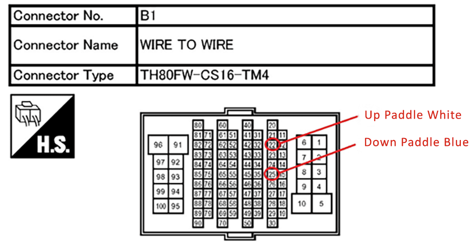
To set up gear shifting, see Gear Request, Gear Automatic and Gear Shift groups in the Package.