This targeted Package, used with an activated MoTeC M150 ECU, is a fully programmable replacement for the factory-fitted Toyota 86 ECU.
It is also compatible with Subaru BRZ and Scion FR-S models from 2012 onward.
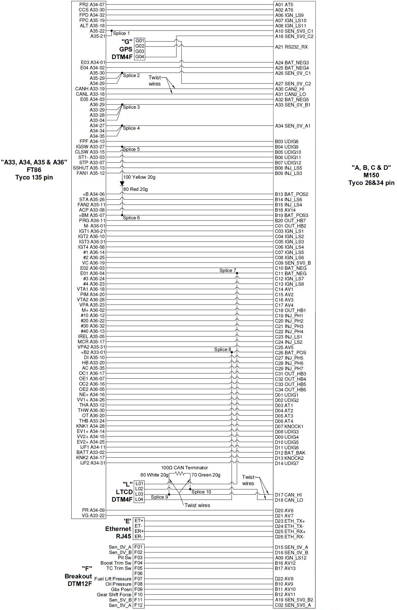
An optional Adaptor Loom is available: 61264 – TOYOTA 86 M150 ADAPTOR LOOM.
61264 Rev A Adaptor Looms are suited to Model Year 2012-2016 only.
61264 Rev B Adaptor Looms are suited to Model Year 2012-2016 and Model year 2017+.
Model Year 2017 and later vehicles use a different Fuel Pressure Direct sensor which requires an additional wire in the adaptor loom (fitted to Rev B Adaptor Looms). If Rev A looms are used, the Fuel Pressure Direct will not be properly sensed and the car may not start.
Rev B Adaptor Looms have a label on the plastic bag which reads ‘SPU61264 TOYOTA FT86 LOOM Rev 00:00 02/10/2018’ or later date. Looms manufactured before 02/10/2018 are Rev A and not suitable for Model Year 2017 and later.
Rev B Adaptor Looms can be identified by examining the DTM12 pin breakout connector: Rev A Looms have a brown wire to pin 6; Rev B Looms do not.
Package variants on MoTeC online are named for 2012-2016 models or 2017+ models as the Fuel Pressure Direct sensor calibration and Fuel Injector Linearisation calibrations are different.
If the optional adaptor loom is used, install as follows:
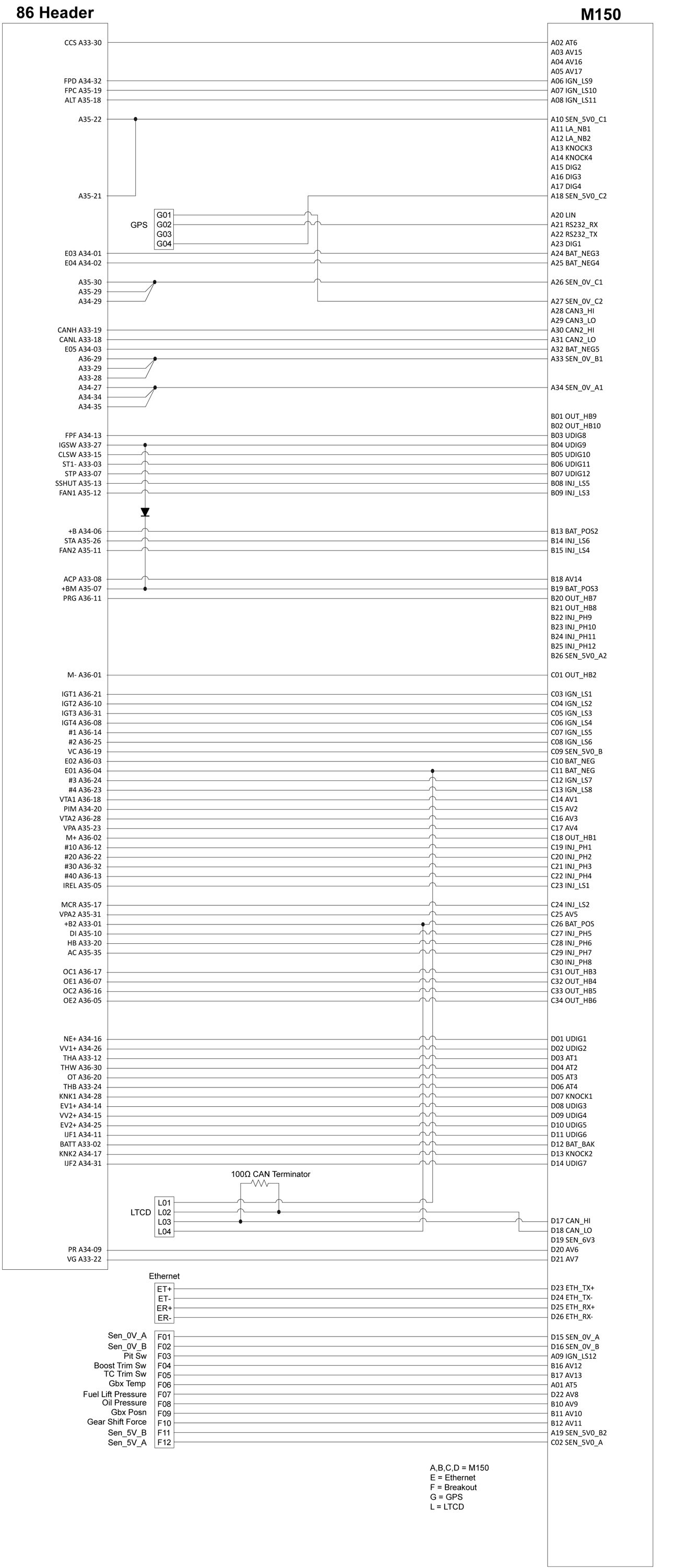
If the optional adaptor loom is not used, the wiring schematic in this document should be used as a reference for wiring installations. As input and output resource allocations in the M150 ECU are not fixed, the M150 ECU Package may be altered to suit other pin allocations.
Several changes were made for 2017+ models which must be accommodated in package settings:
Camshafts
2017 and later model employ mid-lock camshafts which have their adjustment range extended by about 20 degrees. In the case of inlet camshafts this allows the normal 42 (approximate) degrees of advance along with 20 degrees of retard. To ensure that these camshafts are in the zero position for engine start (rather than fully retarded inlet cams) a mechanical lock system secures the cam in the zero position when no control current flows through the oil solenoid. When the engine is stopped and control ceases the camshaft will 'wind down' to the mid-lock (zero) position by mechanical drag on the cam distribution system.
Whereas previous camshafts are controlled with a duty cycle range of perhaps 20 to 80%, mid-lock camshafts will return to the 'lock' position with less than perhaps 35% duty cycle. The active region of advance and retard is exercised between perhaps 40% and 90% duty cycle.
Therefore it is important to use appropriate settings for 2012-2016 or 2017+ models in the cam control groups: if the 2012-2016 settings are used with the later mid-lock cams it is possible to lose control of the cams or for them to return to the lock position when not expected. Numerous settings are critical in this regard:
| Feature | 2012 - 2016 models | 2017+ models |
| Exhaust Camshaft Bank 1 / 2 Position Offset | perhaps 0 to -2 degrees | perhaps -16 to -18 degrees |
| Exhaust Camshaft Bank 1 /2 Actuator Minimum / Maximum | perhaps 40% to 90% | perhaps 50% to 70% (see note below about mid-lock region) |
| Exhaust Camshaft Bank 1 /2 Feed Forward | perhaps 53.5% | perhaps 59% |
| Inlet Camshaft Bank 1 / 2 Position Offset | perhaps 1 to 2 degrees | perhaps -16 to -18 degrees |
| Inlet Camshaft Bank 1 /2 Actuator Minimum / Maximum | perhaps 30% to 90% | perhaps 20% to 60% (see note below about mid-lock region) |
| Inlet Camshaft Bank 1 /2 Feed Forward | perhaps 49% | perhaps 42% |
Note: Actuator Minimum / Maximum duty cycle values refer to the Control value limit before the output polarity is calculated. Therefore for an inlet camshaft with inverting polarity the mid-lock region corresponds to 0% to 35% output duty cycle, which is 65% to 100% control value (before Polarity calculation). Therefore the Actuator Maximum setting of 60% is the critical one to provide a guard-band which will prevent mid-lock operation.
For the exhaust camshafts with normal polarity the mid-lock region corresponds to 0 to 50% output duty cycle, which is 0% to 50% control value (no Polarity inversion). Therefore the Actuator Minimum setting of 50% is the critical one to provide a guard-band which will prevent mid-lock operation.
Crankshaft Rotation Sensor
2012 -2016 models use a magnetic reluctance sensor for the Crankshaft (Reference) signal. 2017+ models use a hall sensor.
Fuel Pressure Direct Pressure Sensor
2012 - 2016 models use a single-output sensor, wired from OE Pin A34-09 to M1 pin AV6.
2017+ models use a dual-output sensor with the existing signal to AV6 covering only a small part of the overall pressure range. An additional output which covers the full range is now wired from OE pin A34-07 to M1 pin AT5. A new sensor calibration is used.
Airbox Mass Flow Sensor, Fuel Pressure Direct Pump Offset, Fuel Injector Primary Linearisation, Fuel Injector Primary Reference Flow, Fuel Injector Secondary Contribution:
The calibrations for these devices are marginally different but nonetheless should be set for the according year model.
There are two variants of the vehicle starting system: conventional key start or push button start:
Both systems require the clutch to be fully depressed for the start solenoid to engage.
There are two variants of the vehicle transmission: manual or automatic.
These options affect the internal CAN messaging between the M1 ECU and the OE systems.
Compressor operation is requested by the OE air conditioner system (Toyota 86 Air Conditioner Request). The M1 ECU operates the compressor clutch relay (AC relay) based on the CAN request, along with configurable enable conditions for:
All of these conditions must be met, along with the OE request, for the compressor to operate. Default settings are used for enable components which are not required.
In addition, Idle Control may be adjusted by means of the Air Conditioner Idle Aim Compensation and Air Conditioner Idle Mass Flow Feed Forward settings.
This product mimics operation of the original alternator system.
No user interaction or settings are required.
A simplified purge strategy is used. Purge solenoid flow has been characterised for the OE installation and the Fuel Purge Solenoid Flow and Fuel Purge Solenoid Flow Inverse tables should not be altered.
While this product uses some sensor information provided by these systems (for example Wheel Speeds), no further interaction occurs.
Any operation of these systems that does not require engine ECU interaction (for example VSC Disable Switch) will function normally.
Allows mapping of the VSC Disable Switch and the VSC Sport Mode Switch into the M1 traction system. Refer to the help in the Package for 'Toyota 86 VSC Disable Switch'.
This product mimics operation of the original fuel system:
The OE direct injection fuel pump has been characterised and settings in the Fuel Pressure Direct group should not require adjustment.
Balance between primary (direct) and secondary (port) injection is controlled by the Fuel Injector Secondary Contribution Main table. The Fuel Injector Secondary Contribution value may be overridden if the primary fuel system fails, in which case 100% port injection is used.
Note: Pin A01 functionality differs between Rev A and Rev B variants, as detailed below.
| Pin Number | Designation | Full Name | OE Pin | Function |
|---|---|---|---|---|
| A01 Rev A Only | AT5 | Analogue Temperature Input 5 | F06 | Gearbox Temperature - optional (2012-2016 models) |
| A01 Rev B Only | AT5 | Analogue Temperature Input 5 | A34-7 | Fuel Pressure Direct Bank 2 Sensor (2017+ Models) |
| A02 | AT6 | Analogue Temperature Input 6 | A33-30 | Cruise Control Switch (future option) |
| A03 | AV15 | Analogue Voltage Input 15 | Not Used | |
| A04 | AV16 | Analogue Voltage Input 16 | Not Used | |
| A05 | AV17 | Analogue Voltage Input 17 | Not Used | |
| A06 | IGN_LS9 | Low Side Ignition 9 | A34-32 | Fuel Pressure Direct Bank 2 Pump A Output |
| A07 | IGN_LS10 | Low Side Ignition 10 | A35-19 | Fuel Pump Control |
| A08 | IGN_LS11 | Low Side Ignition 11 | A35-18 | Alternator Field Control |
| A09 | IGN_LS12 | Low Side Ignition 12 | F03 | Pit Switch (optional) |
| A10 | SEN_5V0_C1 | Sensor 5.0V C | A35-22, A35-21 | Sensor Supply Analogue |
| A11 | LA_NB1 | Lambda Narrow Input 1 | Not Used | |
| A12 | LA_NB2 | Lambda Narrow Input 2 | Not Used | |
| A13 | KNOCK3 | Knock Input 3 | Not Used | |
| A14 | KNOCK4 | Knock Input 4 | Not Used | |
| A15 | DIG2 | Digital Input 2 | Not Used | |
| A16 | DIG3 | Digital Input 3 | Not Used | |
| A17 | DIG4 | Digital Input 4 | Not Used | |
| A18 | SEN_5V0_C2 | Sensor 5.0V C | G04 | GPS Supply |
| A19 | SEN_5V0_B2 | Sensor 5.0V B | F11 | Sensor Supply Options Connector |
| A20 | LIN | LIN Bus | Not Used | |
| A21 | RS232_RX | RS232 Receive | G02 | GPS Receive |
| A22 | RS232_TX | RS232 Transmit | Not Used | |
| A23 | DIG1 | Digital Input 1 | Not Used | |
| A24 | BAT_NEG3 | Battery Negative | A34-01 | Power Ground |
| A25 | BAT_NEG4 | Battery Negative | A34-02 | Power Ground |
| A26 | SEN_0V_C1 | Sensor 0V C | A35-20, A35-29, A34-29 | Sensor Zero Volts Analogue |
| A27 | SEN_0V_C2 | Sensor 0V C | G01 | GPS Zero Volts |
| A28 | CAN3_HI | CAN Bus 3 High | Not Used | |
| A29 | CAN3_LO | CAN Bus 3 Low | Not Used | |
| A30 | CAN2_HI | CAN Bus 2 High | A33-19 | 500k CAN to Vehicle |
| A31 | CAN2_LO | CAN Bus 2 Low | A33-18 | 500k CAN to Vehicle |
| A32 | BAT_NEG5 | Battery Negative | A34-03 | Power Ground |
| A33 | SEN_0V_B1 | Sensor 0V B | A36-29, A33-29, A33-28 | Sensor Zero Volts Analogue |
| A34 | SEN_0V_A1 | Sensor 0V A | A34-34, A34-27, A34-35 | Sensor Zero Volts Analogue |
| Pin Number | Designation | Full Name | OE Pin | Function |
|---|---|---|---|---|
| B01 | OUT_HB9 | Half Bridge Output 9 | Not Used | |
| B02 | OUT_HB10 | Half Bridge Output 10 | Not Used | |
| B03 | UDIG8 | Universal Digital Input 8 | Not Used | Fuel Pressure Direct Pump Feedback |
| B04 | UDIG9 | Universal Digital Input 9 | A33-27 | Ignition Switch |
| B05 | UDIG10 | Universal Digital Input 10 | A33-15 | Clutch Switch |
| B06 | UDIG11 | Universal Digital Input 11 | Normal Open | Stop Switch Brake Lights |
| B07 | UDIG12 | Universal Digital Input 12 | Normal Closed | Stop Switch Brake Lights |
| B08 | INJ_LS5 | Low Side Injector 5 | A35-13 | SSHUT EFI Relays |
| B09 | INJ_LS3 | Low Side Injector 3 | A35-12 | FAN1 |
| B10 | AV9 | Analogue Voltage Input 9 | F08 | Oil Pressure (optional) |
| B11 | AV10 | Analogue Voltage Input 10 | F09 | Gearbox Position (optional) |
| B12 | AV11 | Analogue Voltage Input 11 | F10 | Gear Shift Force (optional) |
| B13 | BAT_POS | Battery Positive | A34-06 | Switched Supply |
| B14 | INJ_LS6 | Low Side Injector 6 | A35-26 | STA Starter Relay |
| B15 | INJ_LS4 | Low Side Injector 4 | A35-11 | FAN2 |
| B16 | AV12 | Analogue Voltage Input 12 | F04 | Boost Trim Switch (optional) |
| B17 | AV13 | Analogue Voltage Input 13 | F05 | TC Trim Switch (optional) |
| B18 | AV14 | Analogue Voltage Input 14 | A33-08 | ACP Air Conditioner Refrigerant Switch |
| B19 | BAT_POS | Battery Positive | A35-07 | Switched Supply |
| B20 | OUT_HB7 | Half Bridge Output 7 | A36-11 | Purge Solenoid |
| B21 | OUT_HB8 | Half Bridge Output 8 | Not Used | |
| B22 | INJ_PH9 | Peak Hold Injector 9 | Not Used | |
| B23 | INJ_PH10 | Peak Hold Injector 10 | Not Used | |
| B24 | INJ_PH11 | Peak Hold Injector 11 | Not Used | |
| B25 | INJ_PH12 | Peak Hold Injector 12 | Not Used | |
| B26 | SEN_5V0_A | Sensor 5.0V A | Not Used | Sensor Supply Analogue |
| Pin Number | Designation | Full Name | OE Pin | Function |
|---|---|---|---|---|
| C01 | OUT_HB2 | Half Bridge Output 2 | A36-01 | Throttle Servo Motor |
| C02 | SEN_5V0_A | Sensor 5.0V A | F12 | Sensor Supply Options Connector |
| C03 | IGN_LS1 | Low Side Ignition 1 | A36-21 | Ignition.Cylinder 1.Output |
| C04 | IGN_LS2 | Low Side Ignition 2 | A36-10 | Ignition.Cylinder 2.Output |
| C05 | IGN_LS3 | Low Side Ignition 3 | A36-31 | Ignition.Cylinder 3.Output |
| C06 | IGN_LS4 | Low Side Ignition 4 | A36-08 | Ignition.Cylinder 4.Output |
| C07 | IGN_LS5 | Low Side Ignition 5 | A36-14 | #1 Direct Injector |
| C08 | IGN_LS6 | Low Side Ignition 6 | A36-25 | #2 Direct Injector |
| C09 | SEN_5V0_B | Sensor 5.0V B | A36-19 | Sensor Supply Analogue |
| C10 | BAT_NEG1 | Battery Negative | A36-03 | Power Ground |
| C11 | BAT_NEG2 | Battery Negative | A36-04, L01 | Power Ground, LTC Ground |
| C12 | IGN_LS7 | Low Side Ignition 7 | A36-24 | #3 Direct Injector |
| C13 | IGN_LS8 | Low Side Ignition 8 | A36-23 | #4 Direct Injector |
| C14 | AV1 | Analogue Voltage Input 1 | A36-18 | VTA1 Throttle Servo Position Main |
| C15 | AV2 | Analogue Voltage Input 2 | A34-20 | PIM Inlet Manifold Pressure |
| C16 | AV3 | Analogue Voltage Input 3 | A36-28 | VTA2 Throttle Servo Position Tracking |
| C17 | AV4 | Analogue Voltage Input 4 | A35-23 | VPA Throttle Pedal Main |
| C18 | OUT_HB1 | Half Bridge Output 1 | A36-02 | Throttle Servo Motor + |
| C19 | INJ_PH1 | Peak Hold Injector 1 | A36-12 | #10 Port Injector |
| C20 | INJ_PH2 | Peak Hold Injector 2 | A36-22 | #20 Port Injector |
| C21 | INJ_PH3 | Peak Hold Injector 3 | A36-32 | #30 Port Injector |
| C22 | INJ_PH4 | Peak Hold Injector 4 | A36-13 | #40 Port Injector |
| C23 | INJ_LS1 | Low Side Injector 1 | A35-05 | Ignition Relay |
| C24 | INJ_LS2 | Low Side Injector 2 | A35-17 | DBW Relay |
| C25 | AV5 | Analogue Voltage Input 5 | A35-31 | VPA2 Throttle Pedal Tracking |
| C26 | BAT_POS | Battery Positive | A33-01 | Switched Supply |
| C27 | INJ_PH5 | Peak Hold Injector 5 | A35-10 | DI Fuel Pump Enable |
| C28 | INJ_PH6 | Peak Hold Injector 6 | A33-20 | HB Blower Motor Relay |
| C29 | INJ_PH7 | Peak Hold Injector 7 | A35-35 | AC Air Conditioner Heater Relay |
| C30 | INJ_PH8 | Peak Hold Injector 8 | Not Used | |
| C31 | OUT_HB3 | Half Bridge Output 3 | A36-17 | OC1 Inlet Camshaft Bank 1 Actuator |
| C32 | OUT_HB4 | Half Bridge Output 4 | A36-07 | OE1 Exhaust Camshaft Bank 1 Actuator |
| C33 | OUT_HB5 | Half Bridge Output 5 | A36-16 | OC2 Inlet Camshaft Bank 2 Actuator |
| C34 | OUT_HB6 | Half Bridge Output 6 | A36-05 | OE2 Exhaust Camshaft Bank 2 Actuator |
| Pin Number | Designation | Full Name | OE Pin | Function |
|---|---|---|---|---|
| D01 | UDIG1 | Universal Digital Input 1 | A34-16 | NE+ Engine Speed |
| D02 | UDIG2 | Universal Digital Input 2 | A34-26 | VV1+ Inlet Camshaft Bank 1 Position |
| D03 | AT1 | Analogue Temperature Input 1 | A33-12 | THA Inlet Manifold Temperature |
| D04 | AT2 | Analogue Temperature Input 2 | A36-30 | THW Coolant Temperature |
| D05 | AT3 | Analogue Temperature Input 3 | A36-20 | OT Engine Oil Temperature |
| D06 | AT4 | Analogue Temperature Input 4 | A33-24 | THB Battery Temperature |
| D07 | KNOCK1 | Knock Input 1 | A34-28 | KNK1 Ignition Knock Sensor Bank 1 |
| D08 | UDIG3 | Universal Digital Input 3 | A34-14 | EV1+ Exhaust Camshaft Bank 1 Position |
| D09 | UDIG4 | Universal Digital Input 4 | A34-15 | VV2+ Inlet Camshaft Bank 2 Position |
| D10 | UDIG5 | Universal Digital Input 5 | A34-25 | EV2+ Exhaust Camshaft Bank 1 Position |
| D11 | UDIG6 | Universal Digital Input 6 | A34-11 | Injector Feedback 1 |
| D12 | BAT_BAK | Battery Backup | A33-02 | Keep Alive Memory Power |
| D13 | KNOCK2 | Knock Input 2 | A34-17 | KNK2 Ignition Knock Sensor Bank 2 |
| D14 | UDIG7 | Universal Digital Input 7 | A34-31 | Injector Feedback 2 |
| D15 | SEN_0V_A | Sensor 0V A | F01 | Sensor Zero Volts Options Connector |
| D16 | SEN_0V_B | Sensor 0V B | F02 | Sensor Zero Volts Options Connector |
| D17 | CAN1_HI | CAN Bus 1 High | L03 | 1M CAN Bus to LTC |
| D18 | CAN1_LO | CAN Bus 1 Low | L02 | 1M CAN Bus to LTC |
| D19 | SEN_6V3 | Sensor 6.3V | Internal Use | |
| D20 | AV6 | Analogue Voltage Input 6 | A34-09 | Fuel Rail Pressure (2012-2016 models) |
| D21 | AV7 | Analogue Voltage Input 7 | A33-22 | VG Mass Air Flow |
| D22 | AV8 | Analogue Voltage Input 8 | F07 | Fuel Lift Pressure (optional) |
| D23 | ETH_TX+ | Ethernet Transmit+ | Ethernet Green/White | |
| D24 | ETH_TX- | Ethernet Transmit- | Ethernet Green | |
| D25 | ETH_RX+ | Ethernet Receive+ | Ethernet Orange/White | |
| D26 | ETH_RX- | Ethernet Receive- | Ethernet |
Note: Pin F06 applies only to Rev A Loom variants.
| Pin Number | Designation | Full Name | M150 Pin | Function |
|---|---|---|---|---|
| F01 | SEN_0V_A | Sensor 0V A | D15 | |
| F02 | SEN_0V_B | Sensor 0V B | D16 | |
| F03 | IGN_LS12 | Low Side Ignition 12 | A09 | Pit Switch |
| F04 | AV12 | Analogue Voltage Input 12 | B16 | Boost Trim Switch |
| F05 | AV13 | Analogue Voltage Input 13 | B17 | TC Trim Switch |
| F06 Rev A Only | AT5 | Analogue Temperature Input 5 | A01 | Gearbox Temperature (2012-2016 models) |
| F07 | AV8 | Analogue Voltage Input 8 | D22 | Fuel Lift Pressure |
| F08 | AV9 | Analogue Voltage Input 9 | B10 | Oil Pressure |
| F09 | AV10 | Analogue Voltage Input 10 | B11 | Gearbox Position |
| F10 | AV11 | Analogue Voltage Input 11 | B12 | Gear Shift Force |
| F11 | SEN_5V0_B2 | Sensor 5.0V B2 | A19 | |
| F12 | SEN_5V0_A | Sensor 5.0V A | C02 |
If you are interested in purchasing this product contact an Authorised MoTeC Dealer.
Download this package from MoTeC Online.
This page shows the relevant downloads for this product. For a full selection of MoTeCs downloads visit the Downloads page.
To keep up-to-date with the latest webinars or software you can subscribe to our mailing lists and we will send you a message when new items are released.
To sign-up for a mailing list click the "SIGN-UP: WEBINAR NEWS" or "SIGN-UP: SOFTWARE RELEASE" button below.