The
The anti-reflective, high contrast display is clear and vibrant in direct sunlight. Numerous supplied display layouts offer fixed graphics with
The
The
The anti-reflective, high contrast display is clear and vibrant in direct sunlight. Numerous supplied display layouts offer fixed graphics with
The
IP rating is dependant upon the user ensuring that the connector entries are waterproof, which, as a minimum, requires all unused wire cavities on the connector to be plugged.
(* available via upgrades )
This pinout is suitable for cables identified as Revision: A and Revision: B on the affixed label.
| RJ45 | M170/M182/M190 | L180/C185/C187/C1812 | |||||||
|---|---|---|---|---|---|---|---|---|---|
| Pin | Function | Revision | MoTeC Colour | Pin Numbering | M170 Pin | M182/M190 Pin | Function | L180/C185/ C187/C1812 Pin | Function |
| 1 | Ethernet TX+ | Rev A & Rev B | Orange-White | 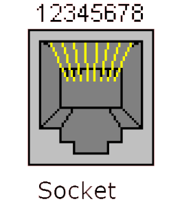 | 55 | C33 | Ethernet RX+ | 77 | Ethernet RX+ |
| 2 | Ethernet TX– | Rev A & Rev B | Orange | 61 | C26 | Ethernet RX– | 78 | Ethernet RX– | |
| 3 | Ethernet RX+ | Rev A | Green-White | 48 | C41 | Ethernet TX+ | 67 | Ethernet TX+ | |
| Rev B | Green | ||||||||
| 6 | Ethernet RX– | Rev A | Green | 47 | C34 | Ethernet TX– | 68 | Ethernet TX– | |
| Rev B | Green-White | ||||||||
The Display Logger should be connected via the CAN bus to any current MoTeC ECU and any number of other CAN devices. See the following example.

Detailed wiring information is available in the User Manual at https://www.motec.com.au/downloads
When using older MoTeC ECUs like M4/M48/M8, the Display Logger should be connected via RS232. For some ECUs, a PCI cable may also be required.
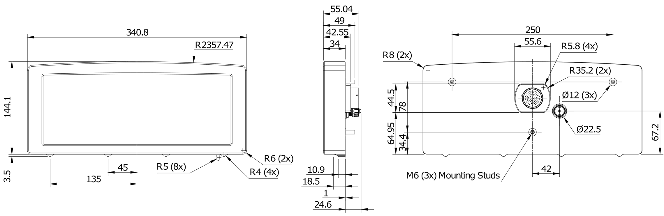
Measurements in mm.
Mating Connector: Part number 68086
| Pin | Name | Standard Function |
|---|---|---|
| 1 | AV15 | Analogue Voltage Input 15 (with I/O upgrade) |
| 2 | AV16 | Analogue Voltage Input 16 (with I/O upgrade) |
| 3 | AV17 | Analogue Voltage Input 17 (with I/O upgrade) |
| 4 | AV18 | Analogue Voltage Input 18 (with I/O upgrade) |
| 5 | AV19 | Analogue Voltage Input 19 (with I/O upgrade) |
| 6 | 0V | Sensor 0 V |
| 7 | BAT– | Battery Negative |
| 8 | BAT+ | Battery Positive |
| 9 | AUX1 | Auxiliary Output 1 |
| 10 | AUX2 | Auxiliary Output 2 |
| 11 | AUX3 | Auxiliary Output 3 |
| 12 | AUX4 | Auxiliary Output 4 |
| 13 | AUX5 | Auxiliary Output 5 |
| 14 | AUX6 | Auxiliary Output 6 |
| 15 | RS232-2 TX | RS232-2 Transmit Output |
| 16 | RS232-2 RX | RS232-2 Receive Input |
| 17 | 0V | Sensor 0 V |
| 18 | 5V | Sensor 5 V |
| 19 | AV7 | Analogue Voltage Input 7 |
| 20 | AV8 | Analogue Voltage Input 8 |
| 21 | AV9 | Analogue Voltage Input 9 |
| 22 | AV10 | Analogue Voltage Input 10 |
| 23 | AV11 | Analogue Voltage Input 11 (with I/O upgrade) |
| 24 | AV12 | Analogue Voltage Input 12 (with I/O upgrade) |
| 25 | AV13 | Analogue Voltage Input 13 (with I/O upgrade) |
| 26 | AV14 | Analogue Voltage Input 14 (with I/O upgrade) |
| 27 | 0V | Sensor 0 V |
| 28 | 5V | Sensor 5 V |
| 29 | VID1 | Video Input 1 |
| 30 | VID0V | Video 0 V |
| 31 | VID2 | Video Input 2 |
| 32 | VID3 | Video Input 3 |
| 33 | 0V | Sensor 0 V |
| 34 | AT1 | Analogue Temp Input 1 |
| 35 | AT2 | Analogue Temp Input 2 |
| 36 | AT3 | Analogue Temp Input 3 |
| 37 | AT4 | Analogue Temp Input 4 |
| 38 | AT5 | Analogue Temp Input 5 (with I/O upgrade) |
| 39 | AT6 | Analogue Temp Input 6 (with I/O upgrade) |
| 40 | 0V | Sensor 0 V |
| 41 | AT7 | Analogue Temp Input 7 (with I/O upgrade) |
| 42 | AT8 | Analogue Temp Input 8 (with I/O upgrade) |
| 43 | 0V | Sensor 0 V |
| 44 | 5V | Sensor 5 V |
| 45 | AV1 | Analogue Voltage Input 1 |
| 46 | AV2 | Analogue Voltage Input 2 |
| 47 | AV3 | Analogue Voltage Input 3 |
| 48 | AV4 | Analogue Voltage Input 4 |
| 49 | AV5 | Analogue Voltage Input 5 |
| 50 | AV6 | Analogue Voltage Input 6 |
| 51 | 0V | Sensor 0 V |
| 52 | DIG1 | Digital Input 1 |
| 53 | DIG2 | Digital Input 2 |
| 54 | DIG3 | Digital Input 3 |
| 55 | DIG4 | Digital Input 4 |
| 56 | 0V | Sensor 0 V |
| 57 | SW1 | Switch Input 1 |
| 58 | SW2 | Switch Input 2 |
| 59 | CAN4L | CAN 4 Low |
| 60 | CAN4H | CAN 4 High |
| 61 | 0V | Sensor 0 V |
| 62 | 8V | Sensor 8 V |
| 63 | SPD1 | Speed Input 1 |
| 64 | SPD2 | Speed Input 2 |
| 65 | SPD3 | Speed Input 3 |
| 66 | SPD4 | Speed Input 4 |
| 67 | E-TX+ | Ethernet Transmit + |
| 68 | E-TX- | Ethernet Transmit – |
| 69 | AV20 | Analogue Voltage Input 20 (with I/O upgrade) |
| 70 | RS232-1 TX | RS232 Transmit Output |
| 71 | CAN3L | CAN 3 Lo |
| 72 | CAN3H | CAN 3 Hi |
| 73 | CAN1L | CAN 1 Lo |
| 74 | CAN1H | CAN 1 Hi |
| 75 | CAN2L | CAN 2 Lo/RS232 Ground Input |
| 76 | CAN2H | CAN 2 Hi/RS232 Receive Input |
| 77 | E-RX+ | Ethernet Receive + |
| 78 | E-RX– | Ethernet Receive – |
| 79 | RS232-1 RX | RS232 Receive Input |
If you are interested in purchasing this product contact an Authorised MoTeC Dealer.
This page shows the relevant downloads for this product. For a full selection of MoTeCs downloads visit the Downloads page.
To keep up-to-date with the latest webinars or software you can subscribe to our mailing lists and we will send you a message when new items are released.
To sign-up for a mailing list click the "SIGN-UP: WEBINAR NEWS" or "SIGN-UP: SOFTWARE RELEASE" button below.