The MoTeC Logo
Welcome
Products
Downloads
Training
Forum
FAQ
Careers
Dealers
Products
The MoTeC Logo
Welcome Products Downloads Training Forum FAQ Careers Dealers
The MoTeC Logo
EDL3 - Obsolete
EDL3 - Obsolete
EDL3 - Obsolete
Part No: #18016

OVERVIEW

The Enclosed Dash Logger (EDL3) is a combined fully programmable data logger and powerful control device in one lightweight unit.

Based on the ADL3, it is supplied in an enclosed unit providing the flexibility to connect a display suitable for your application or to use as a 'black box' type data logger. It provides all the advanced features of MoTeC's ADL3 Dash Logger, including warning alarms, lap times, fuel calculations, minimum corner speeds, maximum straight speeds and more.

The EDL3 performs calculations, acquiring data from other MoTeC devices such as an ECU, Dash Logger and VIMs, which enable it to log more than 300 inputs, including high resolution sensor inputs.

FEATURES

  • Suitable for bikes, cars, marine and industrial applications
  • Supports Wideband Lambda from MoTeC PLMs or LTCs
  • Easily integrates with MoTeC CAN based products such as ECUs, expanders, lap timing devices and shift lights
  • More than 300 sensor inputs, using VIM input expanders
  • GPS Lap Timing
  • Tell Tales
  • Diagnostic Logging
  • Preserved Channels
  • Running Min/Max, Timers, PID Control, Telemetry, Engine Log

ACCESORIES

  • Standard Ethernet cable
  • 61213 – ADL3 loom
  • 61131 – Ethernet cable, unterminated, 2 metre

UPGRADES

  • Data Logging: Increases internal logging memory to 250 MB
  • Pro Analysis: Provides access to advanced i2 Pro data analysis software
  • Telemetry: Enables transmission of live data from the vehicle
  • Remote Logging: Enables converting telemetry data into a log file
  • 52 I/O: Provides additional input/output functionality consisting of:
    • 14 extra Analogue voltage inputs (AV11 to AV24, see pinout)
    • 4 extra Analogue temperature inputs (AT5 to AT8, see pinout)
    • 4 extra Auxiliary outputs (AUX5 to AUX8, see pinout)

SPECIFICATIONS

Logging
  • 16 MB standard logging memory (250 MB optional)
  • Logging rates up to 1000 samples per second
  • Fast Ethernet download
Inputs
  • 10 x Analogue voltage inputs (24 optional)
  • 4 x Analogue temperature inputs (8 optional)
  • 4 x Digital inputs
  • 4 x Speed inputs with voltage measuring capability
  • 4 x Switched inputs
  • Compatible with VIM input expanders
Outputs
  • 4 x PWM, digital or switched outputs (8 optional)
  • Compatible with up to 2 E888/E816 input/output expanders
Internal Sensors
  • 3-axis accelerometer, detection range: +/- 5G
  • Dash temperature sensor
  • Sensor supply voltage
  • Battery voltage
Communications
  • 2 x CAN with individually programmable CAN bus speeds
  • 1 x RS232

SOFTWARE

Windows-based software designed for setup and management of the display* and data logging* system, that provides:

  • Configuration of the inputs, ouputs, LEDs*, display*, data logging* and calculations
  • Offline generation of a configuration file that can then be sent to the device.
  • Channel monitoring
  • Firmware updating and extensive help screens

* Where applicable based on the device.

DIMENSIONS AND MOUNTING

Dimensions are in mm. Ensure product is not stressed when mounted.

ETHERNET WIRING

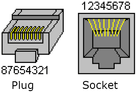
Ethernet Connector MoTeC Loom Colour
Pin Function Pin Function
1 ethernet TX + orange/white ethernet RX +
2 ethernet TX - orange ethernet RX -
3 ethernet RX + green/white ethernet TX +
6 ethernet RX - green ethernet TX -
The wiring specified is the preferred cross-over configuration. However, the wiring can also be configured as straight-through. Cat 5 Ethernet cable must be used.

Pin Numbering

ECU WIRING

When using an M4, M48 or M8 ECU, the should be connected via RS232. For some ECUs, a PCI cable may also be required.

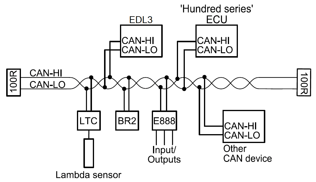
The Display Logger should be connected via the CAN bus when using a ‘hundred series’ ECU(M400/M600/M800/M880) or M84, and any number of other CAN devices. See the following example.

Detailed wiring information is available in the user manual at www.motec.com/downloads.

PINOUT

Mating connector: Part number 68086

Pin Name Function
1 AV15 Analogue Voltage Input 15 (with 52 I/O upgrade)
2 AV16 Analogue Voltage Input 16 (with 52 I/O upgrade)
3 AV17 Analogue Voltage Input 17 (with 52 I/O upgrade)
4 AV18 Analogue Voltage Input 18 (with 52 I/O upgrade)
5 AV19 Analogue Voltage Input 19 (with 52 I/O upgrade)
6 0V Sensor 0 V
7 BAT- Battery Negative
8 BAT+ Battery Positive
9 AUX1 Auxiliary Output 1
10 AUX2 Auxiliary Output 2
11 AUX3 Auxiliary Output 3
12 AUX4 Auxiliary Output 4
13 AUX5 Auxiliary Output 5 (with 52 I/O upgrade)
14 AUX6 Auxiliary Output 6 (with 52 I/O upgrade)
15 AUX7 Auxiliary Output 7 (with 52 I/O upgrade)
16 AUX8 Auxiliary Output 8 (with 52 I/O upgrade)
17 0V Sensor 0 V
18 5V Sensor 5 V
19 AV7 Analogue Voltage Input 7
20 AV8 Analogue Voltage Input 8
21 AV9 Analogue Voltage Input 9
22 AV10 Analogue Voltage Input 10
23 AV11 Analogue Voltage Input 11 (with 52 I/O upgrade)
24 AV12 Analogue Voltage Input 12 (with 52 I/O upgrade)
25 AV13 Analogue Voltage Input 13 (with 52 I/O upgrade)
26 AV14 Analogue Voltage Input 14 (with 52 I/O upgrade)
27 0V Sensor 0 V
28 5V Sensor 5 V
29 AV21 Analogue Voltage Input 21 (with 52 I/O upgrade)
30 AV22 Analogue Voltage Input 22 (with 52 I/O upgrade)
31 AV23 Analogue Voltage Input 23 (with 52 I/O upgrade)
32 AV24 Analogue Voltage Input 24 (with 52 I/O upgrade)
33 0V Sensor 0 V
34 AT1 Analogue Temp Input 1
35 AT2 Analogue Temp Input 2
36 AT3 Analogue Temp Input 3
37 AT4 Analogue Temp Input 4
38 AT5 Analogue Temp Input 5 (with 52 I/O upgrade)
39 AT6 Analogue Temp Input 6 (with 52 I/O upgrade)
40 0V Sensor 0 V
41 AT7 Analogue Temp Input 7 (with 52 I/O upgrade)
42 AT8 Analogue Temp Input 8 (with 52 I/O upgrade)
43 0V Sensor 0 V
44 5V Sensor 5 V
45 AV1 Analogue Voltage Input 1
46 AV2 Analogue Voltage Input 2
47 AV3 Analogue Voltage Input 3
48 AV4 Analogue Voltage Input 4
49 AV5 Analogue Voltage Input 5
50 AV6 Analogue Voltage Input 6
51 0V Sensor 0 V
52 DIG1 Digital Input 1
53 DIG2 Digital Input 2
54 DIG3 Digital Input 3
55 DIG4 Digital Input 4
56 0V Sensor 0 V
57 SW1 Switch Input 1
58 SW2 Switch Input 2
59 SW3 Switch Input 3
60 SW4 Switch Input 4
61 0V Sensor 0 V
62 8V Sensor 8 V
63 SPD1 Speed Input 1
64 SPD2 Speed Input 2
65 SPD3 Speed Input 3
66 SPD4 Speed Input 4
67 E-TX+ Ethernet Transmit +
68 E-TX- Ethernet Transmit -
69 AV20 Analogue Voltage Input 20 (with 52 I/O upgrade)
70 TX RS232 Output
71 0V 0 V CAN
72 8V 8 V CAN
73 CAN0L CAN 0 Low
74 CAN0H CAN 0 High
75 CAN1L CAN 1 Low
76 CAN1H CAN 1 High
77 E-RX+ Ethernet Receive +
78 E-RX- Ethernet Receive -
79 RX RS232 Input

DOWNLOADS

User Manuals & Guides
Name
Version / Part
Published
Download
Name, Version / Part, Published
Name
Version / Part
Published
Download
EDL3 ADL3 User Manual
18016
Jan 2014
Download
EDL3 ADL3 User Manual
18016
Jan 2014
EDL3 ADL3 User Manual
18016
Jan 2014
Download
Useful Links

This page shows the relevant downloads for this product. For a full selection of MoTeCs downloads visit the Downloads page.


To keep up-to-date with the latest webinars or software you can subscribe to our mailing lists and we will send you a message when new items are released.

To sign-up for a mailing list click the "SIGN-UP: WEBINAR NEWS" or "SIGN-UP: SOFTWARE RELEASE" button below.

OVERVIEW

FEATURES

ACCESSORIES

UPGRADES

SPECIFICATIONS

SOFTWARE

DIMENSIONS AND MOUNTING

ETHERNET WIRING

ECU WIRING

PINOUT

DOWNLOADS