MoTeC's
The module replaces conventional relays, fuses and circuit breakers to simplify wiring and switch requirements, while increasing reliability.

MoTeC's
The module replaces conventional relays, fuses and circuit breakers to simplify wiring and switch requirements, while increasing reliability.
To communicate to the PC, a CAN connector must be wired into the CAN bus. To connect the PDM directly to the CAN connector, wire according to the following table.
| PDM Pin | PDM Name | CAN Connector Pin | CAN Connector Wire |
|---|---|---|---|
| CAN Lo | 4 | Green | |
| CAN Hi | 5 | White | |
| 0 V | 1 | Black |
Suitable wire gauges are 24# to 20# for the 8 A outputs and 20# to 16# for the 20 A outputs. The wire gauge must be chosen to suit the current consumed by the connected device and to ensure that the voltage drop is acceptable. In a long run it may be necessary to use a heavier gauge wire to minimise voltage drop. The wire gauge must also be compatible with the connector pin; using a smaller than recommended wire gauge may result in a poor crimp.
37 pin Autosport connector
Mating connector #68089
| Pin | Function |
|---|---|
| A_1 | Digital/Switch Input 1 |
| A_2 | Digital/Switch Input 2 |
| A_3 | Digital/Switch Input 3 |
| A_4 | Digital/Switch Input 4 |
| A_5 | Digital/Switch Input 5 |
| A_6 | 0 V |
| A_7 | 0 V |
| A_8 | 0 V |
| A_9 | 0 V |
| A_10 | CAN Low |
| A_11 | CAN High |
| A_12 | Digital/Switch Input 6 |
| A_13 | Digital/Switch Input 7 |
| A_14 | Digital/Switch Input 8 |
| A_15 | Digital/Switch Input 9 |
| A_16 | Digital/Switch Input 10 |
| A_17 | Digital/Switch Input 11 |
| A_18 | Digital/Switch Input 12 |
| A_19 | Digital/Switch Input 13 |
| A_20 | Digital/Switch Input 14 |
| A_21 | Digital/Switch Input 15 |
| A_22 | 0 V |
| A_23 | 0 V |
| A_24 | 0 V |
| A_25 | 0 V |
| A_26 | Digital/Switch Input 16 |
| A_27 | Digital/Switch Input 17 |
| A_28 | Digital/Switch Input 18 |
| A_29 | Digital/Switch Input 19 |
| A_30 | Digital/Switch Input 20 |
| A_31 | Digital/Switch Input 21 |
| A_32 | Digital/Switch Input 22 |
| A_33 | Digital/Switch Input 23 |
| A_34 | Not Connected |
| A_35 | Not Connected |
| A_36 | Not Connected |
| A_37 | Not Connected |
26 pin Autosport connector
Mating connector #65040
| Pin | Function |
|---|---|
| B_A | 8 A Output 9 |
| B_B | 8 A Output 10 |
| B_C | 8 A Output 11 |
| B_D | 8 A Output 12 |
| B_E | 8 A Output 13 |
| B_F | 8 A Output 14 |
| B_G | 8 A Output 15 |
| B_H | 8 A Output 16 |
| B_J | 8 A Output 17 |
| B_K | 8 A Output 18 |
| B_L | 8 A Output 19 |
| B_M | 8 A Output 20 |
| B_N | 8 A Output 21 |
| B_P | 8 A Output 22 |
| B_R | 8 A Output 23 |
| B_S | 8 A Output 24 |
| B_T | 8 A Output 25 |
| B_U | 8 A Output 26 |
| B_V | 8 A Output 27 |
| B_W | 8 A Output 28 |
| B_X | 8 A Output 29 |
| B_Y | 8 A Output 30 |
| B_Z | 8 A Output 31 |
| B_a | 8 A Output 32 |
| B_b | Batt – |
| B_c | Batt – |
1 pin waterproof connector
Mating connector:
#68093 (wire gauge #6 AWG)
#68094 (wire gauge #4 AWG)
| Pin | Function |
|---|---|
| C_1 | Batt + |
8 pin waterproof connector
Mating connector: #68092 (Deutsch AS616-08SN)
| Pin | Function |
|---|---|
| D_A | 20 A Output 1 |
| D_B | 20 A Output 2 |
| D_C | 20 A Output 3 |
| D_D | 20 A Output 4 |
| D_E | 20 A Output 5 |
| D_F | 20 A Output 6 |
| D_G | 20 A Output 7 |
| D_H | 20 A Output 8 |
This product is designed for use in a vehicle. As such, this product complies with the following standard:
This product is designed for an internal operating temperature range of -40 °C to 85 °C.
It should be installed in a location with sufficient air circulation and be shielded against thermal emissions from surrounding components.
Do not attempt to open and/or repair the device.
For repairs, contact and return the product via your local Authorised MoTeC Dealer.


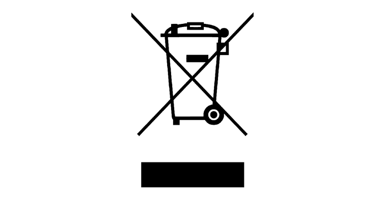
This product should be disposed of in accordance with relevant national regulations for disposal of electronic waste. It does not contain hazardous materials which might be subject to specific materials regulations.
MoTeC Pty. Ltd.
If you are interested in purchasing this product contact an Authorised MoTeC Dealer.
This page shows the relevant downloads for this product. For a full selection of MoTeCs downloads visit the Downloads page.
To keep up-to-date with the latest webinars or software you can subscribe to our mailing lists and we will send you a message when new items are released.
To sign-up for a mailing list click the "SIGN-UP: WEBINAR NEWS" or "SIGN-UP: SOFTWARE RELEASE" button below.
