The MoTeC Logo
Welcome
Products
Downloads
Training
Forum
FAQ
Careers
Dealers
Products
The MoTeC Logo
Welcome Products Downloads Training Forum FAQ Careers Dealers
The MoTeC Logo
3 Force Combined Sensor
Part No: #57213

OVERVIEW

This multi-faceted, Inertial Measurement Unit (IMU) has been designed specifically for motorsport, providing triple axis sensing of G-Force and Gyroscopic measurements. It also provides Compass (magnetic field) measurements.

The sensing range of each sensor has been tailored to suit a wide range of applications that experience high levels of dynamic motion. Each of the three axes (X, Y, Z) is orthogonal to the others, measuring positive and negative forces.

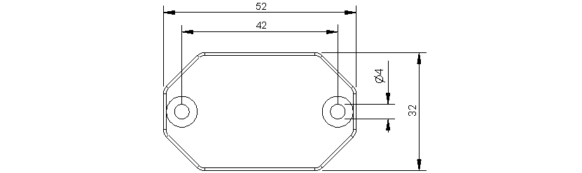
A compact and robust design ensures the 3Force unit is well suited the harsh motorsport environment.

FEATURES

  • Simultaneous measurement of G-Force, Gyroscopic and Magnetic Sensing (compass)
  • Triple axis sensing of all parameters
  • CAN bus interface with a high level of configurability
  • Flexible CAN bus address and data rates
  • Extensive customisation of the data output
  • Rugged design
  • Compact and low weight - less than 55 grams
  • Cost competitive
  • Spare processing capability for custom firmware
  • Upgradeable - allowing for enhanced functionality

SPECIFICATIONS

General Specifications
Parameter Min Typical Max Units
CAN Speed 125 K 1 1 MB baud
Supply Voltage 5 24 V sensor supply
Supply Current - 20 40 mA
Operational Temperature -20 - 70 degrees C

Dimensions: 52 x 32 x 15 mm

Weight: <55 grams (inc. pigtail loom)

Enclosure material: CNC Machined Anodised Aluminium 6016-T6

Heatshrink: Raychem DR-25

Connector Wire: Mil-W-22759/16

G-Force (Acceleration) Sensor
Parameter Min Typical Max Units
Measurement Range (16 g) -16 - +16 g
Stability - +/-0.015 - % per degree C
Nonlinearity - +/-0.3 - %
Inter-Axis Alignment Errors - +/-0.1 - %
Cross-Axis Sensitivity - +/-1 - %
CAN Bus Rate 1 50 500 Hz

Report Resolution: 1 mg (1000 counts per 1 g)

Gyroscopic (Rotation) Sensor
Parameter Min Typical Max Units
Measurement Range - 500 - degrees per second
CAN Bus Rate 1 50 500 Hz

Reported Resolution: 0.1 degrees per second

Internal Sample Rate: 800 Hz

Magnetic (Compass) Sensor
Parameter Min Typical Max Units
CAN Bus Rate 1 20 100 Hz

Internal Sample Rate: 75 Hz

The sensor is capable of detecting the earth's magnetic field, although it is affected by the presence of ferrous objects at very short range.

Note:
  • The CAN bus speed is selected when the sensor is purchased. It may be changed at a later stage.

CAN BUS ADDRESSES

The sensor transmits three sequential CAN bus messages. The default addresses for the CAN bus messages are:

  • 0x610 - X, Y and Z axis G-Force Data
  • 0x611 - X, Y and Z axis Gyroscopic Data
  • 0x612 - X, Y and Z axis Compass Data

COMPATIBILITY

MoTeC Display Loggers and Enclosed Loggers.

WIRING

The sensor is supplied with a pigtail loom and power is supplied via 5 volts.

The 3Force outputs are generated as messages on the CAN bus. There is no CAN termination resistor in the sensor.

4 Pin Connector

Mating connector # 68054

Wire Colour Function
Red Supply Voltage (5 V)
Green CAN High/ CAN +
Blue CAN Low/ CAN -
Black 0 V/ Chassis

DIMENSIONS

Measurements in mm.

PURCHASING

If you are interested in purchasing this product contact an Authorised MoTeC Dealer.

DOWNLOADS

Useful Links

This page shows the relevant downloads for this product. For a full selection of MoTeCs downloads visit the Downloads page.


To keep up-to-date with the latest webinars or software you can subscribe to our mailing lists and we will send you a message when new items are released.

To sign-up for a mailing list click the "SIGN-UP: WEBINAR NEWS" or "SIGN-UP: SOFTWARE RELEASE" button below.

OVERVIEW

FEATURES

SPECIFICATIONS

CAN BUS ADDRESSES

COMPATIBILITY

WIRING

DIMENSIONS

PURCHASING

DOWNLOADS