The MoTeC Logo
Welcome
Products
Downloads
Training
Forum
FAQ
Careers
Dealers
Products
The MoTeC Logo
Welcome Products Downloads Training Forum FAQ Careers Dealers
The MoTeC Logo
D153 Dash Manager User Manual
Image of D153 Dash Manager User Manual
Part No: #18027

OVERVIEW

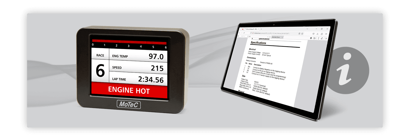
D153 - COLOUR DISPLAY INSTALLATION MANUAL

DASH MANAGER SOFTWARE VERSION

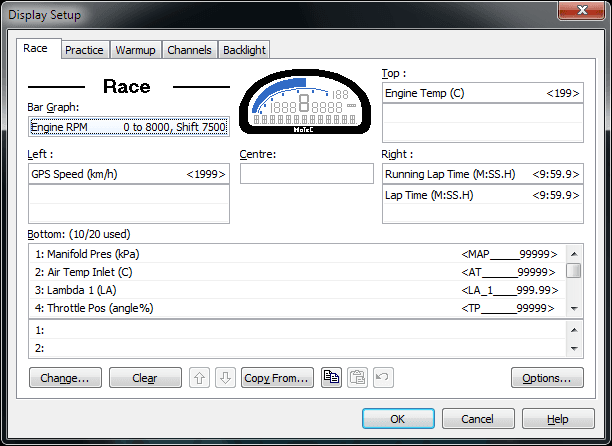
This manual contains information for configuration and installation of the D153 when using Dash Manager software for programing.

The Dash manager software only allows for the use of fixed format display layouts.

For customisable display layout options use the Display Creator software version.

INSTALLATION

Mechanical installation

The D153 is designed primarily as a steering wheel mounted device; it must be used as it is delivered, without disassembly.

To comply with EMC requirements, the case is designed to act as a heat sink for the display and to protect the components inside. There is no warranty for units that have been disassembled or removed from the original case.

It is important that the case is not removed or tampered with and that the unit is not completely enclosed when installed. Complete enclosure of the D153 will reduce cooling. If the display does start to overheat, the D153 will automatically reduce the backlight brightness to reduce temperature.➩ It is normal for the case to get hot, even too hot to handle. Setting the brightness to 50% or less is sufficient for many applications and will reduce the amount of heat generated.Do not remove any part of the casing. The case provides electromagnetic screening to avoid interference with other equipment, and is also essential for thermal management. Thermal management may be compromised if mounted in a confined space, refer to the operating temperature Specifications and the Mechanical installation instructions.

Wiring

As the D153 is intended for steering wheel installation, there are no external connectors on the display. Instead, there are two wiring looms, one with 9 wires and one with 10. These looms connect power, CAN and additional switches and dials to the D153.

Wiring Notes
Wiring Notes
Power Run the power wires down the steering column (normally through a curly cord) to a power supply.
CAN Run the CAN wires down the steering column and connect to the vehicle CAN bus. The CAN bus wires must be twisted together. Important: depending on the wiring design, a CAN terminating resistor may be needed on the steering wheel. All CAN bus wiring must follow CAN bus wiring standards.
Switches SW All of the switch SW inputs are pulled up with 10k to 4.0V. When used as a switch, they should be connected across the switch to the 0V wire.
Analogue inputs AN
  • The analogue inputs are pulled up with 10k to 4.0V. When used as a switch, they should be connected across the switch to the 0V wire.
  • When used as an analogue input, they should be used with a variable resistance dial that pulls the AN input progressively to 0V.
  • The analogue inputs are designed for use with multi-position dials on steering wheels. They are not designed to be used as an input for high precision sensors, such as pressure sensors.
Do not pull the Switch or Analogue inputs up to Battery Positive. Any input pin pulled up above 7V will affect the readings of all other inputs.

CONFIGURATION

All configuration and setup activities for the D153 in this manual are conducted using the MoTeC Dash Manager software.

For Display Creator configuration use the Display Creator software manual.

Setup

The Display Setup window shown below is used to customise where to display channels on the D153. All the modes on the Display Setup window are available on the D153, along with most of the other configurations available in the software. This includes such things as labels, overrides, units etc.

The D153 receives CAN messages from the Dash/Enclosed Logger that indicate which channel should go into what location on the D153 colour display.

D1 Transmit template

The D1 Transmit template is used to transmit messages from the Dash/Enclosed Logger to the D153.

In the Connections/Communication window, add the supplied D1 Transmit template. No customisation of this template is required as it is pre-configured to send the details configured in the Display Setup window.

The Transmitted Channels available in the D1 Transmit template allow setting of options as described in the following table.

Transmitted Channels Description
D1 Display mode Can be configured to allow the user to change which background to use. This can also be set as a fixed value using the Constants setup. A value of 17 displays a black background on the D153, while any other value displays the white background.
D1 Backlight brightness Allows the D153 backlight to be set to a fixed channel, or configured to be altered via a switch or a dial. This switch or dial could come from the steering wheel itself via one of the D153 inputs.
D1 Warning light This is used by the D153 to change the bottom row colour to Red when active. This is generally configured to be set as active when the Data Logger Warning Light channel is active.
D1 Receive template

The D1 Receive template is used to receive the messages from the D153 buttons and dials. These channels will be received into the pre-defined template, where the Dash/Enclosed Logger can use them.

Received Channels Description
Batt Volts D1 The diagnostic channel that shows the current battery voltage at the D153.
D1 Input 1-8 The 8 analogue inputs from the D153. These inputs will show a 0-100% channel as a percentage of 4V on that input pin.
D1 Switch 1-6 The 6 switch inputs that will show only an On or Off (1 or 0) value depending on the state of the switch.

OVERVIEW

INSTALLATION

CONFIGURATION