The MoTeC Logo
Welcome
Products
Downloads
Training
Forum
FAQ
Careers
Dealers
Products
The MoTeC Logo
Welcome Products Downloads Training Forum FAQ Careers Dealers
The MoTeC Logo
GPS-L10 User Manual
GPS-L10 User Manual
GPS-L10 User Manual
Image of GPS-L10 User Manual
Part No: #41304 & 41308

USING THE GPS

Description

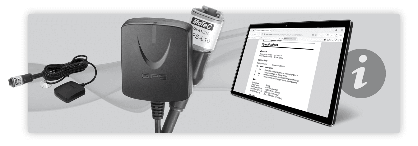
The GPS-L10 is a 10 Hz GPS unit suitable for use only with MoTeC Dash/Enclosed Loggers (excluding original ADLs). It is configured at a fixed baud rate of 38400.

The GPS-L10 is suitable for the high dynamics of motor sport applications. The unit has a built in antenna and provides speed and position information, as well as altitude, heading, date, time and GPS statistics.

In circuit racing, a GPS unit can be a cost effective alternative to the traditional lap timing system. When using a MoTeC Dash/Enclosed Logger, the position of the start/finish line can be marked either by a push button operated by the driver when passing the line or by entering the coordinates directly into the data acquisition system. This position can then be used by the Dash/Enclosed Logger as a beacon to calculate the lap time and by the data analysis software to indicate the start of each lap.

The speed information can be used for display and logging purposes, eliminating the need for wheel speed sensors. This is particularly useful for marine applications as there are no wheel speeds available.

GPS position information can be used in MoTeC's i2 data analysis software to show and compare the driven lines and to create track maps. The driven lines can also be plotted over a Google Earth image, allowing circuit racers and rally drivers to see the path travelled in a real life context.

Mounting

The GPS unit has an integrated antenna and should be mounted on an external horizontal surface that has a clear view of the sky. The unit should be mounted away from sources of interference including other antennas.

If mounting on a non metallic surface it may be necessary to add a metallic ground plane under the unit to improve the signal level. The ground plane should be at least 150 mm (6 in) square and may be made of aluminium or steel.

GPS OPERATION

In normal use the GPS unit should start operating within 15 to 45 seconds of power up, however during first start-up or if the GPS has been moved to a new location it may take up to 5 minutes before it gains satellite lock and starts transmitting data.

To check that the GPS is operating correctly check the number of satellites being received using the logging device Manager software.

The GPS requires a minimum of 4 satellites to function. Normally, however, the GPS should see at least 7 satellites. If the GPS sees more satellites it will improve accuracy and minimise satellite drop out.

Loss of signal may occur when the satellites are obscured by trees, buildings or a bridge. The GPS will take a second or two to recover from this situation.

ELECTRICAL CONNECTIONS

The GPS unit transmits GPS data to the logging device via an DTM connector using the RS232 serial communication protocol.

The wiring between the GPS connector and the logging device should be as short as practical.

4 Pin Connector

Mating connector # 68054

Pin Name Description
1 Bat - Connect to Battery Negative on the logging device
2 TX Connect to RX pin on logging device
3 RX Don't connect (this pin is only used for programming)
4 5V Connect to 5 V sensor supply on the logging device

The following table shows how to wire the GPS unit to a number of MoTeC logging devices.

Model Pin Name Compatibility
122 B11, B14 Udig 6 or 7 Revision Q or higher only
M130 B11, B14 Udig 6 or 7 Revision Q or higher only
M141 A21 RS232_RX
M142 A21 RS232_RX
M150 A21 RS232_RX
M170 Not compatible
M181 A15 RS232_RX
M182 A15 RS232_RX
M190 A15 RS232_RX
Model Pin Name
C125 25 & 28 RS232-1 RX & RS232-2 RX
C127 25 & 28 RS232-1 RX & RS232-2 RX
C1212 25 & 28 RS232-1 RX & RS232-2 RX
C185 79 & 16 RS232-1 RX & RS232-2 RX
C187 79 & 16 RS232-1 RX & RS232-2 RX
C1812 79 & 16 RS232-1 RX & RS232-2 RX
CDL3 28 RX RS232 Input
L120/L120 USB 25 & 28 RS232-1 RX & RS232-2 RX
L180 79 &16 RS232-1 RX & RS232-2 RX
Some models of Dash/Enclosed Logger can be configured to receive RS232 data on an unused CAN high pin. Refer to Dash Manager settings.
Model Part No Connector
C125 Race Loom Terminated 62204 Direct connection to GPS
CDL3 Terminated Loom 62203 Direct connection to GPS

GPS CONFIGURATION

Ensure that Logging is Enabled on your MoTeC Dash/Enclosed Logger.
Software

  • Dash Manager.
  • M1 Tune.

GPS

The GPS-L10 comes preconfigured from MoTeC to suit MoTeC M1 ECU's and Dash/Enclosed Loggers.

Dash/Enclosed loggers

Connections setup

  • Confirm GPS interface wiring e.g. GPS is wired to the RS232-2 RX pin of the Dash/Enclosed Logger.
  • Plug in the Ethernet connection to your lap top.
  • Open Dash Manager.
  • Get Configuration from the Online menu.
  • Click Connections menu bar.
  • Click Communication menu item.
  • Select the interface (e.g. RS232-2 RX) from the list then click Select.Choose the interface that suites your wiring connections.
  • Select from the preconfigured list GPS - Standard RMC GGA template and click OK.
  • Choose the Baud Rate of 38400 from the list and click OK.

Logging setup

  • Open Dash Manager.
  • Click on the Functions menu bar click Logging menu item.
  • In the Logging setup window click the Add button.The minimum GPS channels to log are GPS Latitude, GPS Longitude and GPS Speed.
  • Add the GPS channels GPS Latitude, GPS Longitude and GPS Speed. The other GPS channels are optional.It is recommended to log all GPS channels.
  • Ensure the logging rate for all GPS channels is 20 times/second.
  • Click Send configuration to the Dash/Enclosed Logger.
M1 ECU
M1 ECU’s require a minimum of level 2 Logging to be enabled.

Connections setup

RS232 RX and Udig pin GPS interface configuration.

  • Confirm GPS interface wiring e.g. GPS is wired to the RS232-2 RX pin or Udig pin of the M1 ECU.
  • Plug in the Ethernet connection to your lap top.
  • Open the ECU in M1 Tune.
  • Open the All Calibrate Worksheet.
  • Expand the GPS line item.
  • Set the interface Drop Down to RS232 port.
  • Expand the serial line item.
  • When using a dedicated RS232 ECU pin:
    • Set the port resource Drop Down to RS232.
  • When using a Udig ECU pin:
    • Set the port resource Drop Down to Serial 1 RX or Serial 2 RX.

STC CAN interface configuration

A MoTeC STC (Serial to CAN) #61125 can be used to deliver the GPS serial data output to the CAN bus of an M1 ECU or Dash/Enclosed Logger.Early versions of M130 (prior to rev Q) and M170 ECU's can only receive GPS data via CAN.

  • Open the All Calibrate Worksheet.
  • Expand the GPS line item.
  • Set the interface Drop Down to CAN Bus 1 via STC.
  • Choose one of three CAN Bus options not cuurently being used.M122 and M130 only have 1 CAN bus all other M1 ECU's have 3 CAN buses.
  • In the CAN ID base channel enter 146.

Logging setup

  • In the Menu bar click Tools.
  • Click Edit data Logging.
  • Highlight all GPS channels in the Channel list.
  • Right click highlighted items Select schedule on 20 Hz then click OK.

GPS Beacon

Please refer to LAP in the Firmware help of M1 tune.

DATA ANALYSIS

GPS data analysis requires i2 data analysis software version 1.02 or higher.

All GPS channels (speed, heading, altitude etc.) can be used in the usual way including plotting on a graph.

The GPS position data (latitude and longitude) can also be used for the following:

  • To plot the actual path travelled on a GPS Track component
    • On the Add menu select GPS Track
  • To generate the conventional track map
    • On Tools menu select Track Editor
    • Select Generate Track and then GPS method
  • To plot the path travelled over a Google Earth image
    • On the File menu select Google Earth Export

SPECIFICATIONS

Electrical

  • Power supply voltage 4.0 to 6.0 V
  • Power supply current 38 mA typical
More than 6 V power supply risks damaging the GPS.

Data

  • Output type: RS232
  • Output levels: -5V / 5V (nominal)
  • Baud rate: 38400 (MoTeC default)
  • NMEA sentences: RMC and GGA (MoTeC default)

Physical

  • Antenna: Built into GPS unit
  • Size: 48 mm x 41 mm x 14mm
  • Weight: 106 g
  • Cable length: 1.5 M (#41308) and 2.8 M (#41304) versions available
  • Operating temperature: -30 °C to 80°C
  • Mounting: Magnetic base

GPS Performance

  • Update rate: 10 Hz
  • Satellite channels: 66
  • Reacquisition time: < 1 sec
  • Hot start time: 2 seconds
  • Warm start time 33 seconds
  • Cold start time: 35 seconds
  • Dynamics: 4G

USING THE GPS

GPS OPERATION

ELECTRICAL CONNECTIONS

GPS CONFIGURATION

DATA ANALYSIS

SPECIFICATIONS