The MoTeC Logo
Welcome
Products
Downloads
Training
Forum
FAQ
Careers
Dealers
Products
The MoTeC Logo
Welcome Products Downloads Training Forum FAQ Careers Dealers
The MoTeC Logo
Honda Civic FK8R 2017 M1 Kit
Part No: #11426

OVERVIEW

The updated MoTeC Plug-In ECU Kit for the 10th generation FK8 Honda Civic Type R 2017 - 2020 is a complete motorsport-grade replacement for the factory ECU, using existing wiring, sensors and fuel systems for easy installation.

With the M1 ECU at its core, this updated Plug-In ECU kit unlocks the true performance potential of the K20C turbo engine, with precise control over fuel delivery, ignition timing, throttle response and boost.

For builds pushing beyond factory limitations, the FK8 Plug-In ECU Kit now supports optional secondary port injection, to build on the capability of the OE direct injection system. This opens the door to higher power targets, increased boost and reliable operation on high-ethanol fuel blends.

Integrated with original vehicle systems, the kit retains factory functionality while giving tuners the flexibility and programmable control needed for both immediate gains and long-term development.

This Kit supports OE ECU features, including:

  • Push button start
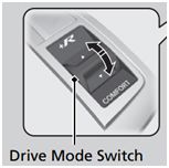
  • Selectable Drive Mode including Comfort, Sport and +R using OE controls
  • Direct Injection with high pressure fuel pump control.
  • Adaptive Cruise Control with OE functionality*
  • Engine speed matching (throttle blip) on downshifts
  • Reverse gear lockout
  • OE dash functionality including warnings

* Refer to the Operation section below for details.

KIT CONTENTS

  • 13142M - M142 ECU MARINE
    • 61612 - M142 HONDA CIVIC ADAPTOR BOX
    • 61404 - M1 ADAPTOR 250MM 26W KEY 1 STUB LOOM
    • 61405 - M1 ADAPTOR 250MM 26W KEY 3 STUB LOOM
    • 61406 - M1 ADAPTOR 250MM 34W KEY 1 STUB LOOM
    • 61407 - M1 ADAPTOR 250MM 34W KEY 2 STUB LOOM
    • 61430 - M1 ADAPTOR LTC LOOM
    • 61800L - LTC - LSU LAMBDA TO CAN LONG LOOM
    • 61613 - M142 HONDA CIVIC MOUNTING KIT
      • 3 x M5 Flat Washers
      • 3 x M5 x 20mm Cap Socket Screws
      • 4 x 4.8 x 200mm Cable Ties
Licence
  • 23320 – M1 LIC - HONDA CIVIC TYPE R K20C

This Licence is required to run the Honda Civic Type R 2017 K20C Package in the M142 ECU.

VEHICLE COMPATIBILITY

This product includes CAN and LIN messaging for full OE vehicle integration. The Package caters for OE vehicle systems such as power steering, ABS, starting system and dashboard.

The following table shows compatible vehicles.

Vehicle Year Badge Comment
Honda Civic 2017 - 2020 Type R K20C, Manual Transmission

Note: This product is not suitable for other Honda Civic variants (e.g, 1.5L engine models)

The Honda Civic FL5 2023 M1 Kit is also availiable, see Datasheet here

FEATURES

  • This kit fully integrates with these original systems:
    • Direct fuel injection
    • Push button start
    • Dashboard
    • Drive Mode
    • Adaptive Cruise Control
    • Engine Speed Matching
    • Electric Power Steering
  • For ease of integration a number of features are pre-configured to suit compatible vehicles:
    • Calibrations for Original Equipment (OE) sensors and engine triggers.
    • Control of Direct Injection fuel system.
    • Reference mode for engine synchronisation.
    • Physical settings for engine displacement, fuel density, stoichiometric ratio, fuel pressure, and injector linearisation, for simplified engine start-up prior to tuning.
    • CAN messaging for OE systems.
    • LIN messaging for control of the OE Alternator.
    • Boost control using wastegate actuator and bypass solenoid.
    • Transient fuelling compensation using physical modelling of fuel film for direct injectors.
    • On-board knock control for each cylinder using the OE knock sensor and selectable centre frequency.
    • Lambda control with included LTC module. Utilises the OE Bosch LSU 4.9 sensor.
    • Idle closed loop control system using ignition and throttle servo actuation.
    • Sensing of OE subsystems
      • Drive Mode switches
      • Engine Oil Pressure
      • Coolant Temperature
      • Boost Pressure
      • Fuel Pressure Direct and Fuel Pressure (low)
      • Vehicle Acceleration and Wheel Speeds
      • Airbox Mass Flow
      • Intake Manifold Pressure and Temperature
      • Clutch Position
      • Throttle Servo and Pedal Position
      • Gear Input Shaft Speed
      • Boost Servo Actuator Position
      • Clutch switch
      • Brake pressure and brake switch
      • Reverse gate
      • Neutral gate
      • Cruise Control switches
    • Control of OE subsystems:
      • Cooling Fan control
      • Variable Valve Lift (VTEC).
      • Fuel Purge Solenoid
      • Turbocharge Wastegate Actuator and Bypass Valve
      • Downshift rev matching
      • Alternator (via LIN)
      • Reverse Gear Lockout Solenoid
      • Air Conditioner Clutch
  • Included GPR features:
    • Engine Load Average channel with tables for engine speed limit, ignition timing trim, fuel mixture aim, boost limit, and throttle limit.
    • Configurable security for multiple users with differing access options.
    • Intercooler temperature and spray control.
    • Lap distance, time and number via BR2 or switched input, with split and sector options.
    • Vehicle speed limiting (pit speed control).
    • Launch control
    • Race time system with tables for ignition timing trim, fuel mixture aim, boost limit, and throttle limit.
    • Configurable anti-lag with ignition timing limit, fuel volume trim, ignition cut, fuel cut, engine speed limit, boost aim and throttle aim tables.
    • Traction control with tables for aim main, aim compensation, control range.
  • Additional optional integrations:
    • The updated FK8 kit now supports fully integrated control of a secondary Port Fuel Injector system with the addition of suitable PFI fuel system hardware.
    • Support of MoTeC devices: E8XX, PDM, SLM, Keypad, Rotary Controller.
    • 8 configurable driver switches, 8 rotary switches and MoTeC Keypad and Rotary Controller support, each with 10 positions that can be simultaneously mapped to launch control, pit switch, anti-lag, traction, race time reset, engine speed limit maximum, throttle lever translation, fuel volume trim, ignition timing, fuel mixture aim, boost limit, traction aim, and traction control range.
    • GPS acquisition and logging via CAN or RS232.
    • ECU CAN Receive from a defined ID base address for data reception from MoTeC devices.
    • Coolant pump output with PWM control.
    • Coolant pump after-run functionality, optionally with additional pump output.
    • Switchable inlet manifold runner with position feedback.
    • Engine run time total for engine hour logging.
    • Pulsed tachometer output with configurable output pin and scaling.
    • Transmission pump output with transmission temperature threshold and hysteresis control.
    • Optional channels for additional sensors via input pin and/or CAN message, including:
      • Ambient Temperature
      • Brake Pressure
      • Coolant Pressure
      • Engine Crankcase Pressure
      • Engine Oil Temperature
      • Exhaust Temperature and Pressure
      • Intercooler Temperature
      • Turbocharger Speed
      • Differential Temperature
      • Fuel Composition, Flow and Temperature
      • Transmission Temperature and Pressure

OPERATION

Reference Mode

The M1 Reference Mode in this Package is locked to the Honda K20C pattern.

ECU Power

The M1 ECU will be powered as follows:

  • M1 ECU power is tied to the vehicle immobiliser system state. From the immobiliser sleep state, if the car is unlocked or a door is opened, the immobiliser system becomes active and the M1 is powered.
  • When the M1 is connected to the M1 Tune application via Ethernet. Once on, power will remain while the M1 remains connected to M1 Tune.
  • With the Ignition off, the vehicle immobiliser system returns to its sleep state and the M1 ECU powers down. This occurs approximately 45 seconds from locking the car or 90 seconds from all doors being closed. If a door is left ajar, the immobiliser and M1 take approximately 20-30 minutes to power down.
  • Resetting the M1 while the ignition is on will interrupt the CAN and LIN communications on their respective vehicle buses causing vehicle modules to display errors on the dash or become inoperative until communications are reset. To avoid this, turn the ignition off before resetting the M1 ECU. See Firmware Updating Procedure below.
Firmware Updating Procedure

The Cooling Fan Low Relay, Cooling Fan High Relay, Power Sub Relay and Turbocharger Bypass Solenoid are controlled via a LIN Communications Bus between the M1 ECU and the updated Honda Civic adaptor box. The process of updating firmware to the M1 ECU causes the LIN Bus to enter a Timeout Error state (Honda Civic LIN Port Diagnostic reports Timeout Error). In this state, the LIN controlled outputs become inoperative and a power cycle of the M1 ECU is required to clear the error.A loss of LIN Bus communications and hence an inoperative Coolant Fan Relay presents an engine overheating risk.

The following procedure needs to be followed when updating Honda Civic Firmware to avoid LIN or CAN bus communications errors.

  1. With the ignition off, opening a door or pressing unlock on the vehicle remote key fob will wake the vehicle immobilizer system and power the M1 ECU.
  2. Connect M1 Tune to the M1 ECU via Ethernet.
  3. Send the updated Firmware to the M1 as normal.
  4. Once the package send is complete, power down the ECU by following the steps below.
    • a. Ensure Ignition is off. Close all doors and lock the vehicle.
    • b. Unplug the Ethernet connection between M1 ECU and M1 Tune.
    • c. Wait approximately 45 seconds.
    • d. Plug the Ethernet cable back into the computer. If M1 Tune can connect to the ECU, the immobilizer sleep state was not achieved and the M1 ECU remained powered. Repeat Step 4b-4d.
    • e. Unlock the car and reconnect the Ethernet cable. M1 Tune should reestablish connection with the M1 ECU.
    • f. Once M1 Tune has connected to the ECU and without pressing the clutch, press Start Button twice to power up the vehicle to Ignition On. Check Honda Civic LIN Diagnostic. If it reports anything other than OK repeat steps 4a-4f prior to starting the engine.
  • Honda Civic LIN Port Diagnostic will report Bit Error once the vehicle is powered up to Ignition. Bit Error does not impact LIN communications.
  • This procedure is only required when updating Firmware (ie, when there is a change to the Firmware version number). A package send to the ECU does not disrupt LIN bus communications.
Engine Start

The OE engine start procedure is maintained in this Package. Note that the key must be inside the vehicle.

With the engine off, depress the clutch and push the engine start button.

Driver Switches

Various in-car switches are acquired over the vehicle CAN buses and assigned to Firmware Resources to allow for mode switching in the ECU. See the Help for the main Honda Civic group in M1 Tune.

Reverse Lockout

The reverse lockout solenoid will not allow reverse gear to be selected while the Vehicle Speed is greater than 5km/h.

Cruise Control

OE Cruise Control functionality has been maintained in this Package. Adaptive Cruise Control (ACC) operation and integration with various vehicle safety systems is performed by the vehicle control systems. The output of the ACC system is then implemented by the M1 ECU as a Cruise Throttle Request. This allows full OE functionality of the Honda ACC system to be maintained including Adaptive Cruise Control, Lane Keeping Assist, and Low Speed Follow where available. Refer to the owner's manual for information on feature availability and operation.

Adjustable Speed Limiter sub-function of the cruise control system available on some FK8 vehicles is not supported by this Package.
Adjustable Driving Modes

Driver selectable Drive Mode functionality has been maintained in this Package.

Refer to the Owner Handbook for more information.

The Driving Mode can also be used as a customisable driver switch within the Package - this driver switch can be mapped to launch control, pit switch, anti-lag, traction, race time reset, engine speed limit maximum, throttle pedal translation, fuel volume trim, ignition timing, fuel mixture aim, boost limit, traction aim, and traction control range.

Engine Mode is linked to the Throttle Pedal Translation table to allow user customisation of throttle response across modes.

Dash Lights

The dashboard Check Engine Light will illuminate when Warning Source is not None.

PGM-FI Warning Light will illuminate according to the Fuel Output Diagnostic.

Engine Oil Pressure Low Warning Light will illuminate according to Engine Oil Pressure Warning.

NOTE: The Engine Oil Level Warning lamp is not supported.

INSTALLATION GUIDE

See below in the "Downloads" section for an "Installation Guide".

M142 PINOUT

M142 Connector A - 34 Way
Mating Connector: Tyco Superseal 34 Position Keying 2 – MoTeC #65067
Pin Designation Full Name Tyco Pin* Honda Pin* Function
A01 AT5 Analogue Temperature Input 5
A02 AT6 Analogue Temperature Input 6
A03 AV15 Analogue Voltage Input 15
A04 AV16 Analogue Voltage Input 16
A05 AV17 Analogue Voltage Input 17
A06 INJ_D1A_NEG Direct Injector 1A - T96-03 T96-18 Fuel Cylinder 1 Primary
A07 INJ_D1A_POS Direct Injector 1A + T96-04 T96-17 Fuel Cylinder 1 Primary
A08 INJ_D1B_POS Direct Injector 1B + Not used - DO NOT CONNECT
A09 INJ_D1B_NEG Direct Injector 1B - Not used - DO NOT CONNECT
A10 SEN_5V0_C1 Sensor 5.0V C T58-45, T58-11, T96-46 T58-23, T58-55, T96-62 Sensor 5V
A11 LA_NB1 Lambda Narrow Input 1
A12 LA_NB2 Lambda Narrow Input 2
A13 KNOCK3 Knock Input 3
A14 KNOCK4 Knock Input 4
A15 DIG2 Digital Input 2
A16 DIG3 Digital Input 3 E23
A17 DIG4 Digital Input 4
A18 SEN_5V0_C2 Sensor 5.0V C
A19 SEN_5V0_B2 Sensor 5.0V B T96-47, T96-45, T96-44, T96-43, T96-20, E04, E05, E06, E07 T96-61, T96-63, T96-64, T96-65, T96-82, E04, E05, E06, E07 Sensor 5V
A20 LIN LIN Bus T96-08 T96-94 Honda Civic LIN Port
A21 RS232_RX RS232 Receive E16
A22 RS232_TX RS232 Transmit
A23 DIG1 Digital Input 1
A24 BAT_NEG Battery Negative T58-02, T58-04, T58-06, E08, E09, E17 T58-01, T58-03, T58-05, E08, E09, E17 ECU Ground, Breakout Ground
A25 BAT_NEG Battery Negative T58-02, T58-04, T58-06, E08, E09, E17 T58-01, T58-03, T58-05, E08, E09, E17 ECU Ground, Breakout Ground
A26 SEN_0V_C Sensor 0V C T58-36, T96-89, T96-64, T96-18 T58-32, T96-31, T96-50, T96-84 Sensor 0V
A27 SEN_0V_C Sensor 0V C
A28 CAN3_HI CAN Bus 3 High T58-39 T58-29 Vehicle Powertrain Bus B (500Kb/s)
A29 CAN3_LO CAN Bus 3 Low T58-52 T58-17 Vehicle Powertrain Bus B (500Kb/s)
A30 CAN2_HI CAN Bus 2 High T58-54, E28 T58-15, E28 Vehicle Powertrain Bus A (500Kb/s)
A31 CAN2_LO CAN Bus 2 Low T58-41, E27 T58-27, E27 Vehicle Powertrain Bus A (500Kb/s)
A32 BAT_NEG Battery Negative T58-02, T58-04, T58-06, E08, E09, E17 T58-01, T58-03, T58-05, E08, E09, E17 ECU Ground, Breakout Ground
A33 SEN_0V_B Sensor 0V B T58-20, T58-07, T96-30, E20, E21, E22, E29, E30, E31 T58-09, T58-10, T96-78, E20, E21, E22, E29, E30, E31 Sensor 0V
A34 SEN_0V_A Sensor 0V A T96-56 T96-58 Sensor 0V
*Tyco pin numbers, listed above, match the pin numbering found on the Tyco connectors fitted to both the OE engine harness and adaptor box. Honda pin numbers, listed above, match the pin numbering found on the Honda electrical schematics.
M142 Connector B - 26 Way
Mating Connector: Tyco Superseal 26 Position Keying 3 – MoTeC #65068
Pin Designation Full Name Tyco Pin* Honda Pin* Function
B01 OUT_HB9 Half Bridge Output 9 T96-95 T96-25 Exhaust Camshaft Rocker Actuator
B02 OUT_HB10 Half Bridge Output 10 T58-18 T58-48 Air Conditioner Clutch
B03 UDIG8 Universal Digital Input 8 T58-47 T58-22 Clutch Switch
B04 UDIG9 Universal Digital Input 9 T96-39 T96-69 Gear Input Shaft Speed Sensor
B05 UDIG10 Universal Digital Input 10 T96-61 T96-53 Airbox Mass Flow Sensor
B06 UDIG11 Universal Digital Input 11 T58-49 T58-20 Engine Start Switch
B07 UDIG12 Universal Digital Input 12 T58-15 T58-51 Driver Switch 1 (Engine Run Switch)
B08 INJ_LS5 Low Side Injector 5 T58-17, T58-29 T58-38, T58-49 Engine Start Motor Relay
B09 INJ_LS3 Low Side Injector 3 T58-42 T58-26 ECU Power Relay
B10 AV9 Analogue Voltage Input 9 T96-38 T96-70 Boost Servo Position Sensor Main
B11 AV10 Analogue Voltage Input 10 T58-24 T58-43 Not Used on FL5
B12 AV11 Analogue Voltage Input 11 T58-10 T58-56 Air Conditioner Refrigerant Pressure Sensor
B13 BAT_POS Battery Positive T58-05, T58-03, T58-01 T58-02, T58-04, T58-06, E01, E02, E10 ECU Power, Breakout Power
B14 INJ_LS6 Low Side Injector 6 T96-68 T96-46 Coolant Fan 1
B15 INJ_LS4 Low Side Injector 4 T58-56 T58-13 Fuel Pump
B16 AV12 Analogue Voltage Input 12 T96-90 T96-30 Gear Neutral Switch
B17 AV13 Analogue Voltage Input 13 T96-92 T96-28 Driver Switch 2 (Neutral Switch 2)
B18 AV14 Analogue Voltage Input 14
B19 BAT_POS Battery Positive T58-01, T58-03, T58-05 T58-02, T58-04, T58-06, E01, E02, E10 ECU Power, Breakout Power
B20 OUT_HB7 Half Bridge Output 7 (-) T96-52 T96-07 Fuel Pressure Direct Bank 1
B21 OUT_HB8 Half Bridge Output 8 (+) T96-76 T96-02 Fuel Pressure Direct Bank 1
B22 INJ_D2A_NEG Direct Injector 2A - T96-02 T96-19 Fuel Cylinder 2 Primary
B23 INJ_D2A_POS Direct Injector 2A + T96-01 T96-20 Fuel Cylinder 2 Primary
B24 INJ_D2B_POS Direct Injector 2B + Not used - DO NOT CONNECT
B25 INJ_D2B_NEG Direct Injector 2B - Not used - DO NOT CONNECT
B26 SEN_5V0_A Sensor 5.0V A T96-41, T96-22 T96-67, T96-80 Sensor 5V

*Tyco pin numbers, listed above, match the pin numbering found on the Tyco connectors fitted to both the OE engine harness and adaptor box. Honda pin numbers, listed above, match the pin numbering found on the Honda electrical schematics.

M142 Connector C - 34 Way
Mating Connector C: Tyco Superseal 34 Position Keying 1 – MoTeC #65044
Pin Designation Full Name Tyco Pin* Honda Pin* Function
C01 OUT_HB2 Half Bridge Output 2 (+) T96-75 T96-03 Throttle Servo Bank 1 Motor
C02 SEN_5V0_A Sensor 5.0V A T96-41 T96-67 Sensor 5V
C03 IGN_LS1 Low Side Ignition 1 T96-55 T96-59 Ignition Cylinder 1
C04 IGN_LS2 Low Side Ignition 2 T96-54 T96-60 Ignition Cylinder 2
C05 IGN_LS3 Low Side Ignition 3 T96-79 T96-41 Ignition Cylinder 3
C06 IGN_LS4 Low Side Ignition 4 T96-78 T96-42 Ignition Cylinder 4
C07 IGN_LS5 Low Side Ignition 5 T58-32 T58-35 Honda Civic Reverse Lockout Relay
C08 IGN_LS6 Low Side Ignition 6 E18
C09 SEN_5V0_B Sensor 5.0V B T58-21, T58-08, T96-42, T96-21 T58-46, T58-58, T96-66, T96-81 Sensor 5V
C10 BAT_NEG Battery Negative T58-02, T58-04, T58-06 E08, E09, E17 T58-01, T58-03, T58-05, E08, E09, E17 ECU Ground, Breakout Ground
C11 BAT_NEG Battery Negative T58-02, T58-04, T58-06, E08, E09, E17 T58-01, T58-03, T58-05, E08, E09, E17 ECU Ground, Breakout Ground
C12 IGN_LS7 Low Side Ignition 7 E25
C13 IGN_LS8 Low Side Ignition 8 E26
C14 AV1 Analogue Voltage Input 1 T58-09 T58-57 Throttle Pedal Sensor Main
C15 AV2 Analogue Voltage Input 2 T58-22 T58-45 Throttle Pedal Sensor Tracking
C16 AV3 Analogue Voltage Input 3 T96-13 T96-89 Throttle Servo Bank 1 Position Sensor Main
C17 AV4 Analogue Voltage Input 4 T96-14 T96-88 Throttle Servo Bank 1 Position Sensor Tracking
C18 OUT_HB1 Half Bridge Output 1 (-) T96-51 T96-08 Throttle Servo Bank 1 Motor
C19 INJ_D3A_POS Direct Injector 3A + T96-25 T96-15 Fuel Cylinder 3 Primary
C20 INJ_D3B_POS Direct Injector 3B + Not used - DO NOT CONNECT
C21 INJ_D4A_POS Direct Injector 4A + T96-28 T96-12 Fuel Cylinder 4 Primary
C22 INJ_D4B_POS Direct Injector 4B + Not used - DO NOT CONNECT
C23 INJ_LS1 Low Side Injector 1 E34
C24 INJ_LS2 Low Side Injector 2 T96-06 T96-96 Fuel Purge Bank 1
C25 AV5 Analogue Voltage Input 5 T96-93 T96-27 Inlet Manifold Pressure Sensor
C26 BAT_POS Battery Positive T58-05, T58-03, T58-01 T58-02, T58-04, T58-06, E01, E02, E10 ECU Power, Breakout Power
C27 INJ_D3A_NEG Direct Injector 3A - T96-26 T96-14 Fuel Cylinder 3 Primary
C28 INJ_D3B_NEG Direct Injector 3B - Not used - DO NOT CONNECT
C29 INJ_D4A_NEG Direct Injector 4A - T96-27 T96-13 Fuel Cylinder 4 Primary
C30 INJ_D4B_NEG Direct Injector 4B - Not used - DO NOT CONNECT
C31 OUT_HB3 Half Bridge Output 3 (-) T96-49 T96-10 Boost Servo Actuator Motor
C32 OUT_HB4 Half Bridge Output 4 (+) T96-73 T96-05 Boost Servo Actuator Motor
C33 OUT_HB5 Half Bridge Output 5 T96-77 T96-01 Exhaust Camshaft Bank 1 Actuator
C34 OUT_HB6 Half Bridge Output 6 T96-53 T96-06 Inlet Camshaft Bank 1 Actuator
*Tyco pin numbers, listed above, match the pin numbering found on the Tyco connectors fitted to both the OE engine harness and adaptor box. Honda pin numbers, listed above, match the pin numbering found on the Honda electrical schematics.
M142 Connector D — 26 way
Mating Connector D: Tyco Superseal 26 Position Keying 1 – MoTeC #65045
Pin Designation Full Name Tyco Pin* Honda Pin* Function
D01 UDIG1 Universal Digital Input 1 T96-33 T96-75 Engine Speed Reference
D02 UDIG2 Universal Digital Input 2 T96-35 T96-73 Inlet Camshaft Bank 1 Position
D03 AT1 Analogue Temperature Input 1 T96-69 T96-45 Inlet Air Temperature Sensor
D04 AT2 Analogue Temperature Input 2 T96-65 T96-49 Coolant Temperature Sensor
D05 AT3 Analogue Temperature Input 3 T96-17 T96-85 Coolant Temperature Sensor 2
D06 AT4 Analogue Temperature Input 4 T96-62 T96-52 Turbocharger Inlet Temperature Sensor
D07 KNOCK1 Knock Input 1 (-) T96-37 T96-71 Knock Cylinder 1, 2, 3, 4
D08 UDIG3 Universal Digital Input 3 T96-57 T96-57 Exhaust Camshaft Bank 1 Position
D09 UDIG4 Universal Digital Input 4 T96-80 T96-40 Not used on FL5
D10 UDIG5 Universal Digital Input 5 T96-66 T96-48 Exhaust Camshaft Rocker Feedback
D11 UDIG6 Universal Digital Input 6 T58-46 T58-07 Gear Reverse Switch
D12 BAT_BAK Battery Backup T58-16 T58-50 Battery Power
D13 KNOCK2 Knock Input 2 (+) T96-12 T96-90 Knock Cylinder 1, 2, 3, 4
D14 UDIG7 Universal Digital Input 7 T58-37 T58-31 Brake Switch
D15 SEN_0V_A Sensor 0V A T96-86, T96-86, T96-34, T96-34, T96-32 T96-34, T96-34, T96-74, T96-74, T96-76 Sensor 5V
D16 SEN_0V_B Sensor 0V B T96-24, T96-91, T96-85, T96-11, T96-07 T96-23, T96-29, T96-35, T96-91, T96-95 Sensor 0V
D17 CAN1_HI CAN Bus 1 High E33 LTC (1Mbps)
D18 CAN1_LO CAN Bus 1 Low E32 LTC (1Mbps)
D19 SEN_6V3 Sensor 6.3V E03
D20 AV6 Analogue Voltage Input 6 T96-88 T96-32 Fuel Pressure Direct Bank 1 Sensor
D21 AV7 Analogue Voltage Input 7 T96-67 T96-47 Engine Oil Pressure Sensor
D22 AV8 Analogue Voltage Input 8 T96-63 T96-51 Boost Pressure Sensor
D23 ETH_TX+ Ethernet Transmit+ Ethernet Green/White PC Communications
D24 ETH_TX- Ethernet Transmit- Ethernet Green PC Communications
D25 ETH_RX+ Ethernet Receive+ Ethernet Orange/White PC Communications
D26 ETH_RX- Ethernet Receive- Ethernet Orange PC Communications
*Tyco pin numbers, listed above, match the pin numbering found on the Tyco connectors fitted to both the OE engine harness and adaptor box. Honda pin numbers, listed above, match the pin numbering found on the Honda electrical schematics.
Breakout Connector

Mating Connector: Tyco Superseal 34 Position Keying 1 – MoTeC #65044

Pin Designation Full Name M142 Pin# Function
E01* BAT_POS Battery Positive B13, B19, C26 LTC DTM Pin 4
E02 BAT_POS Battery Positive B13, B19, C26
E03 SENS_6V3 SEN_6V3 D19
E04 SENS_5V0_B Sensor 5.0V B A19
E05 SENS_5V0_B Sensor 5.0V B A19
E06 SENS_5V0_B Sensor 5.0V B A19
E07 SENS_5V0_B Sensor 5.0V B A19
E08 BAT_NEG Battery Negative A24, A25, A32, C10, C11
E09* BAT_NEG Battery Negative A24, A25, A32, C10, C11 LTC DTM Pin 1
E10 BAT_POS Battery Positive B13, B19, C26
E11 AV13 Analogue Voltage Input 13 B17 Gear Neutral Switch 2
E12 AV15 Analogue Voltage Input 15 A03
E13 AV16 Analogue Voltage Input 16 A04
E14 AV17 Analogue Voltage Input 17 A05
E15 AT5 Analogue Temperature Input 5 A01
E16 RS232RX RS232 Receive A21
E17 BAT_NEG Battery Negative A24, A25, A32, C10, C11
E18 IGN_LS6 Low Side Ignition 6 C08 Fuel Injector Secondary Cylinder 1
E19 AT6 Analogue Temperature Input 6 A02
E20 SENS_0V_B Sensor 0V B A33
E21 SENS_0V_B Sensor 0V B A33
E22 SENS_0V_B Sensor 0V B A33
E23 DIG3 Digital Input 3 A16
E24 UDIG10 Universal Digital Input 10 B05 This pin is only available if the Airbox Mass Flow Sensor is disconnected.
E25 IGN_LS7 Low Side Ignition 7 C12 Fuel Injector Secondary Cylinder 2
E26 IGN_LS8 Low Side Ignition 8 C13 Fuel Injector Secondary Cylinder 3
E27 CAN2LO CAN Bus 2 Low A31 Vehicle Powertrain Bus A (500Kb/s)
E28 CAN2HI CAN Bus 2 High A30 Vehicle Powertrain Bus A (500Kb/s)
E29 SENS_0V_B Sensor 0V B A33 Sensor 0V B
E30 SENS_0V_B Sensor 0V B A33 Sensor 0V B
E31 SENS_0V_B Sensor 0V B A33 Sensor 0V B
E32* CAN1LO CAN Bus 1 Low D18 LTC DTM Pin 2 (1Mb/s)
E33* CAN1HI CAN Bus 1 High D17 LTC DTM Pin 3 (1Mb/s)
E34 INJ_LS1 Low Side Injector 1 D23 Fuel Injector Secondary Cylinder 4

*This pin is connected to the 4-pin DTM connector of the breakout loom that is supplied with the kit.

PURCHASING

If you are interested in purchasing this product contact an Authorised MoTeC Dealer.

PACKAGE DOWNLOAD

Download this package from MoTeC Online.

DOWNLOADS

User Manuals & Guides
Name
Version / Part
Published
Download
Name, Version / Part, Published
Name
Version / Part
Published
Download
M1 Flex Fuel User Guide
Mar 2017
Download
M1 Flex Fuel User Guide
Mar 2017
M1 Flex Fuel User Guide
Mar 2017
Download
M1 Launch Control User Guide
Mar 2017
Download
M1 Launch Control User Guide
Mar 2017
M1 Launch Control User Guide
Mar 2017
Download
Installation Guides
Name
Version / Part
Published
Download
Name, Version / Part, Published
Name
Version / Part
Published
Download
Honda Civic FL5 - FK8 Kit Install Instructions
11418
Jan 2026
Download
Honda Civic FL5 - FK8 Kit Install Instructions
11418
Jan 2026
Honda Civic FL5 - FK8 Kit Install Instructions
11418
Jan 2026
Download
Useful Links

This page shows the relevant downloads for this product. For a full selection of MoTeCs downloads visit the Downloads page.


To keep up-to-date with the latest webinars or software you can subscribe to our mailing lists and we will send you a message when new items are released.

To sign-up for a mailing list click the "SIGN-UP: WEBINAR NEWS" or "SIGN-UP: SOFTWARE RELEASE" button below.

OVERVIEW

KIT CONTENTS

VEHICLE COMPATIBILITY

FEATURES

OPERATION

INSTALLATION GUIDE

M142 PINOUT

PURCHASING

PACKAGE DOWNLOAD

DOWNLOADS