This Kit is temporarily unavailable.
It will be reintroduced soon with updated hardware, providing even more functionality with the same plug-in convenience.
Honda Civic Type R 2017 Paddle Shift M1 Kit
Honda Civic Type R 2017 Paddle Shift M1 Kit
Honda Civic Type R 2017 Paddle Shift M1 Kit
Part No: #23421
This Honda Civic Type R FK8R package is based on MoTeC's successful GPRP-DI package and is available on the MoTeC M142 ECU, it is a versatile and adaptable platform for the operation of this engine.
It is configured to run the HondaCivic K20C Engine with the addition of a paddle shifted gearbox using switched actuators. The package allows for easy changes to engine tuning and hardware.
Along with fuel, ignition, camshaft and turbocharger control, this Package also supports other OE ECU features, including:
- Push button start
- Air conditioner control
- High and low speed fan control
- Adjustable driving mode
- Fuel canister purge valve control
- Engine speed matching (throttle blip) on downshifts
- Alternator control
- Reverse lockout
- Cruise control
Included are many ancillary features common to race cars, such as anti-lag, driver switches (pit switch, launch enable, boost trim etc.), gearbox control, knock control, intercooler sprays, launch control, gearbox coolant pump, gear shift air pump and traction control. It also caters for many systems found on modified road vehicles that may be useful in a racing context, such as air conditioning control.
This product includes CAN messaging for full OE vehicle integration. The Package caters for OE vehicle systems such as power steering, ABS, starting systems and dashboards. The following table shows compatible vehicles.
| Vehicle | Year | Engine |
|---|---|---|
| Honda Civic Type R | 2017 | K20C |
This Package can be used with the M142 HONDA CIVIC FK8R 2017 KIT (#11401).
- Paddle shift gearbox control for sequential gearboxes with switched actuators.
- Paddle Shift Input can be hard wired or received via CAN as either up or down switches or a single linear sensor.
- Optional lockouts for Neutral and Reverse selection.
- Up/Down actuator control, with preload times preceding the shifts and hold time to safely engage gears.
- Configurable Minimum/Maximum blip time on downshifts.
- Multiple gear shift modes such as: manual, automatic, fault modes, switch selection only, disabled.
- Closed loop gear shift strategy including retries for missed shifts.
- Gear Shift actuator air pump support with air pressure monitoring.
- Optional gearbox shift request via Up Shift Switch / Down Shift Switch or Gear lever Force Sensor.
- Drive by wire throttle blip control with engine speed matching.
- Optional throttle blip and engine speed matching when the clutch is engaged.
- Pre-configured calibrations for Original Equipment sensors.
- Pre-configured reference mode for engine synchronisation.
- Pre-configured physical settings for engine displacement, fuel density, stoichiometric ratio, fuel pressure, and injector characterisation, which allow for simplified engine start-up prior to tuning.
- Engine load modelling based on inlet manifold pressure and inlet air temperature, with a pre-configured engine efficiency map that allows for quick and easy engine tuning.
- Pre-configured control of Direct Injector and high pressure pump.
-
Optionally configurable secondary (port injector) fuel control with a tuneable balance table.
Note: Only saturated (high-ohm) secondary injectors are supported in this hardware. Peak-hold (low-ohm) secondary injectors are not supported.
- Optional alternative fuel operation for Flex Fuel using ethanol composition sensor, or Secondary Fuel operation on secondary injectors.
- Closed Loop Lambda control supported; requires optional LTC. OE lambda sensor can be used.
- Pre-configured coolant temp compensations for engine speed limit, ignition timing, fuel volume, fuel mixture, boost limit.
- Pre-configured transient fuelling compensation using physical modelling of fuel film.
- Engine Load Average channel with tables for engine speed limit, ignition timing trim, fuel mixture aim, boost limit, and throttle limit.
- Pre-configured ignition output and coil settings
- Pre-configured on-board knock control for each cylinder using the OE knock sensors and multiple centre frequencies.
- Pre-configured camshaft control of inlet and exhaust cam.
- Pre-configured variable valve lift (VTEC).
- Pre-configured engine start fuel volumes.
- Pre-configured Idle Closed Loop control system using ignition and Drive by Wire actuation.
- Pre-configured Throttle Aim Minimum to control manifold pressure during engine overrun (engine braking control).
- Pre-configured boost control of OE wastegate servo motor. Single and dual wastegate solenoids are also supported.
- Pre-configured turbocharger bypass control.
- Intercooler temperature and spray control.
- Configurable Anti-Lag for single turbo with ignition timing limit, fuel volume trim, ignition cut, engine speed limit, boost aim and throttle aim tables.
- Supports nitrous system with two activation stages and additional fuel pumps, bottle heater control and pressure sensor.
- Configurable Launch Control with tables for engine speed, throttle limit, boost aim and fuel volume trim.
- Traction Control with tables for aim main, aim compensation, control range.
- Pre-configured closed loop alternator system for OE Alternator.
- Pre-configured OE coolant fan output. With support for 2 aftermarket coolant fan outputs (PWM controlled).
- Coolant pump output with PWM control.
- Coolant pump after-run functionality, optionally with additional pump output.
- Supports 2 switchable inlet manifold flaps with position feedback, and 1 switchable inlet manifold runner with position feedback, for variable inlet systems.
- Pre-configured air conditioner control.
- Configurable Fuel pump switched output.
- Closed loop fuel pressure control for lift subsystem.
- Configurable Gearbox position detection
- Configurable Gearbox shift request
- Gearbox shift support with ignition cut, fuel cut, throttle blip and engine speed matching in forward gears.
- Transmission pump output with transmission temperature threshold and hysteresis control.
- Differential pump output with differential temperature threshold and hysteresis control.
- Pre-configured Drive by Wire throttle servo control.
- Pre-configured Throttle Pedal sensor with translation table for each Drive Mode (Sport, Comfort, +R)
- 8 configurable driver switches and 8 rotary switches each with 10 positions that can be simultaneously mapped to launch control, pit switch, anti-lag, traction, race time reset, engine speed limit maximum, throttle pedal translation, fuel volume trim, ignition timing, fuel mixture aim, boost limit, traction aim, and traction control range.
- Vehicle speed limiting (pit speed control).
- Configurable pulsed tachometer output with configurable output pin and scaling.
- Pre-configured vehicle speed measurement using wheel speed sensors.
- Pre-configured warning system that activates engine check light on OE dash (MIL)
- Test settings for most outputs, including injection and ignition outputs, for easier setup.
- Lap distance, time and number via GPS, BR2 or switched input, with split and sector options.
- Race time system with tables for ignition timing trim, fuel mixture aim, boost limit, and throttle limit.
- Engine run time total for engine hour logging.
- GPS acquisition and logging via CAN or RS232.
- GLONASS messaging support on GPS devices.
- Support of MoTeC devices: ADR, E8XX, PDM, SLM, VCS.
- ECU CAN Receive from other MoTeC devices.
- ECU CAN Transmit of the most common channels using standard MoTeC CAN templates.
- Configurable security for multiple users with differing access options.
- Channels for sensors via input pin and/or CAN message, including:
- Airbox Mass Flow*, Temperature and Pressure
- Air Conditioner Refrigerant Pressure*
- Ambient Pressure and Temperature
- Boost Pressure* and Servo Position*
- Brake Pressure Front and Rear
- Brake Switch and Vacuum Pressure
- Clutch Switch, Pressure and Position
- Coolant Pressure and Temperature* (x2)
- Engine Oil Pressure* and Temperature
- Engine Crankcase Pressure
- Exhaust Pressure
- Exhaust Temp (EGT) via TCA Thermocouple Amplifier, Generic CAN, or E888 for Collector and Cylinders 1 to 4.
- Exhaust Lambda via LTC, LTCN, or PLM for Collector and Cylinders 1 to 4.
- Fuel Flow Supply and Return
- Fuel Pressure* and Temperature
- Fuel Composition
- Fuel Tank Level
- Gear Position, Lever Force and Input Shaft Speed
- Inlet Air Temperature and Manifold Pressure*
- Intercooler Temperature
- Steering Angle and Pressure
- Throttle Pedal* and Position*
- Transmission Temperature and Pressure
- Turbocharger Speed, Inlet* and Outlet Temperature
- G-Force (acceleration) - Longitudinal, Lateral, Vertical
- Wastegate Pressure and Position
- Wheel Speed*
* These sensors have been pre-configured with a calibration and settings to match the OE sensor.
Reference Mode
The M1 Reference Mode in this Package is locked to this engine variant.
Power ECU
The M1 ECU will be powered whenever the ignition is on. With the key inside the vehicle, turn the ignition on by pushing the engine start button twice. To turn off, simply push the engine start button once. The ECU power will remain on if the ignition is turned off while the M1 ECU is connected to M1 Tune.
Resetting the M1 while the ignition is on will interrupt the CAN communications on the vehicle CAN bus causing other CAN modules to display errors on the dash. To avoid this, turn the ignition off before resetting the M1 ECU.
Engine Start
The OE engine start procedure is maintained in this Package. Ensure the key must be inside the vehicle. With the engine off, depress the clutch and push the engine start button. |  |
Reverse Lockout
The reverse lockout solenoid will not allow reverse gear to be selected while the Vehicle Speed is greater than 5km/h.
Cruise Control
The Cruise Control functionality of the OE ECU has been maintained in this Package. This includes the Lane Keeping Assist, Adaptive Cruise Control and Low Speed Follow. Refer to the owner's manual for the operation of these features.
Adjustable Driving Modes
The Driving Mode can be changed between Sport, Comfort and +R by toggling the Drive Mode Switch. Changing the driving mode provides alternate settings for Steering, Damper Control and Vehicle Stability Assist. | 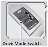 |
The Driving Mode can also be used as a customisable driver switch within the Package - this driver switch can be mapped to launch control, pit switch, anti-lag, traction, race time reset, engine speed limit maximum, throttle pedal translation, fuel volume trim, ignition timing, fuel mixture aim, boost limit, traction aim, and traction control range.
The Driving Mode has been pre-configured to throttle pedal translation to give a more aggressive throttle pedal in +R mode with a relaxed feel in Comfort mode.
Dash Lights
The functionalities of the Engine Check Light (All Warnings), PGMWI Warning Light, Oil Level Warning Light and Oil Pressure Low Warning Light are maintained in this Package. These lights are activated with the associated M1 warning system.
M142 Connector A - 34 Way
Mating Connector: Tyco Superseal 34 Position Keying 2 – MoTeC #65067| Pin | Designation | Full Name | Tyco Pin* | Honda Pin* | Function |
|---|---|---|---|---|---|
| A01 | AT5 | Analogue Temperature Input 5 | |||
| A02 | AT6 | Analogue Temperature Input 6 | |||
| A03 | AV15 | Analogue Voltage Input 15 | |||
| A04 | AV16 | Analogue Voltage Input 16 | |||
| A05 | AV17 | Analogue Voltage Input 17 | |||
| A06 | INJ_D1A_NEG | Direct Injector 1A - | T96-03 | T96-18 | Injector 1 Low |
| A07 | INJ_D1A_POS | Direct Injector 1A + | T96-04 | T96-17 | injector 1 High |
| A08 | INJ_D1B_POS | Direct Injector 1B + | |||
| A09 | INJ_D1B_NEG | Direct Injector 1B - | |||
| A10 | SEN_5V0_C1 | Sensor 5.0V C | T58-11, T96-46 | T58-55, T96-62 | |
| A11 | LA_NB1 | Lambda Narrow Input 1 | |||
| A12 | LA_NB2 | Lambda Narrow Input 2 | |||
| A13 | KNOCK3 | Knock Input 3 | |||
| A14 | KNOCK4 | Knock Input 4 | |||
| A15 | DIG2 | Digital Input 2 | |||
| A16 | DIG3 | Digital Input 3 | |||
| A17 | DIG4 | Digital Input 4 | |||
| A18 | SEN_5V0_C2 | Sensor 5.0V C | T58-45 | T58-23 | |
| A19 | SEN_5V0_B2 | Sensor 5.0V B | T96-47, T96-45, T96-44, T96-43, T96-20 | T96-61, T96-63, T96-64, T96-65,T96-82 | |
| A20 | LIN | LIN Bus | T96-08 | T96-94 | LIN Comms - LIN |
| A21 | RS232_RX | RS232 Receive | |||
| A22 | RS232_TX | RS232 Transmit | |||
| A23 | DIG1 | Digital Input 1 | |||
| A24 | BAT_NEG3 | Battery Negative | T58-06 | T58-01 | Chassis Ground |
| A25 | BAT_NEG4 | Battery Negative | T58-04 | T58-03 | Chassis Ground |
| A26 | SEN_0V_C1 | Sensor 0V C | T58-36, T96-18 | T58-32, T96-84 | |
| A27 | SEN_0V_C2 | Sensor 0V C | |||
| A28 | CAN3_HI | CAN Bus 3 High | T58-39 | T58-29 | CAN B High** |
| A29 | CAN3_LO | CAN Bus 3 Low | T58-52 | T58-17 | CAN B Low** |
| A30 | CAN2_HI | CAN Bus 2 High | T58-54 | T58-15 | CAN A High |
| A31 | CAN2_LO | CAN Bus 2 Low | T58-41 | T58-27 | CAN A Low |
| A32 | BAT_NEG5 | Battery Negative | T58-02 | T58-05 | Chassis Ground |
| A33 | SEN_0V_B1 | Sensor 0V B | T58-20, T58-07, T96-30 | T58-09, T58-10, T96-78 | |
| A34 | SEN_0V_A1 | Sensor 0V A | T96-34, T96-32 | T96-74, T96-76 |
M142 Connector B - 26 Way
Mating Connector: Tyco Superseal 26 Position Keying 3 – MoTeC #65068| Pin | Designation | Full Name | Tyco Pin* | Honda Pin* | Function |
|---|---|---|---|---|---|
| B01 | OUT_HB9 | Half Bridge Output 9 | T96-95 | T96-25 | Rocker Arm Oil Control Solenoid |
| B02 | OUT_HB10 | Half Bridge Output 10 | T58-18 | T58-48 | AC Compressor Clutch Relay |
| B03 | UDIG8 | Universal Digital Input 8 | T58-47 | T58-22 | Clutch Position Switch A |
| B04 | UDIG9 | Universal Digital Input 9 | T96-39 | T96-69 | Input Shaft Speed Sensor |
| B05 | UDIG10 | Universal Digital Input 10 | |||
| B06 | UDIG11 | Universal Digital Input 11 | T58-49 | T58-20 | Starter Switch Signal |
| B07 | UDIG12 | Universal Digital Input 12 | T58-15 | T58-51 | Ignition Signal |
| B08 | INJ_LS5 | Low Side Injector 5 | T58-17 | T58-49 | Starter Cut Relay 1 |
| B09 | INJ_LS3 | Low Side Injector 3 | T58-42 | T58-26 | Main Relay 1 & Ign Coil Relay |
| B10 | AV9 | Analogue Voltage Input 9 | T96-38 | T96-70 | Turbo Wastegate Position Sensor |
| B11 | AV10 | Analogue Voltage Input 10 | T58-24 | T58-43 | Brake Booster Pressure Sensor |
| B12 | AV11 | Analogue Voltage Input 11 | T58-10 | T58-56 | Air Conditioner Pressure Sensor |
| B13 | BAT_POS | Battery Positive | T58-05 | T58-02 | Power Source |
| B14 | INJ_LS6 | Low Side Injector 6 | T58-29 | T58-38 | Starter Cut Relay 2 |
| B15 | INJ_LS4 | Low Side Injector 4 | T58-56 | T58-13 | Fuel Pump Relay |
| B16 | AV12 | Analogue Voltage Input 12 | T96-90 | T96-30 | Neutral Switch 1 |
| B17 | AV13 | Analogue Voltage Input 13 | T96-92 | T96-28 | Neutral Switch 2 |
| B18 | AV14 | Analogue Voltage Input 14 | T96-61 | T96-53 | Mass Airflow Sensor |
| B19 | BAT_POS | Battery Positive | T58-03 | T58-04 | Power Source |
| B20 | OUT_HB7 | Half Bridge Output 7 | T96-52 | T96-07 | High Pressure Fuel Pump |
| B21 | OUT_HB8 | Half Bridge Output 8 | T96-76 | T96-02 | High Pressure Fuel Pump |
| B22 | INJ_D2A_NEG | Direct Injector 2A - | T96-02 | T96-19 | Injector 2 Low |
| B23 | INJ_D2A_POS | Direct Injector 2A + | T96-01 | T96-20 | Injector 2 High |
| B24 | INJ_D2B_POS | Direct Injector 2B + | |||
| B25 | INJ_D2B_NEG | Direct Injector 2B - | |||
| B26 | SEN_5V0_A | Sensor 5.0V A | T96-19 | T96-83 |
*Tyco pin numbers, listed above, match the pin numbering found on the Tyco connectors fitted to both the OE engine harness and adaptor box. Honda pin numbers, listed above, match the pin numbering found on the Honda electrical schematics.
M142 Connector C - 34 Way
Mating Connector C: Tyco Superseal 34 Position Keying 1 – MoTeC #65044| Pin | Designation | Full Name | Tyco Pin* | Honda Pin* | Function |
|---|---|---|---|---|---|
| C01 | OUT_HB2 | Half Bridge Output 2 | T96-75 | T96-03 | Throttle Servo Motor + |
| C02 | SEN_5V0_A | Sensor 5.0V A | T96-41, T96-22 | T96-67, T96-80 | |
| C03 | IGN_LS1 | Low Side Ignition 1 | T96-55 | T96-59 | Ignition 1 |
| C04 | IGN_LS2 | Low Side Ignition 2 | T96-54 | T96-60 | Ignition 2 |
| C05 | IGN_LS3 | Low Side Ignition 3 | T96-79 | T96-41 | Ignition 3 |
| C06 | IGN_LS4 | Low Side Ignition 4 | T96-78 | T96-42 | Ignition 4 |
| C07 | IGN_LS5 | Low Side Ignition 5 | T58-32 | T58-35 | Reverse Lockout Solenoid |
| C08 | IGN_LS6 | Low Side Ignition 6 | T58-19 | T58-47 | Sub Relay |
| C09 | SEN_5V0_B | Sensor 5.0V B | T58-21, T58-08, T96-42, T96-21 | T58-46, T58-58, T96-66, T96-81 | |
| C10 | BAT_NEG1 | Battery Negative | |||
| C11 | BAT_NEG2 | Battery Negative | |||
| C12 | IGN_LS7 | Low Side Ignition 7 | T58-57 | T58-12 | Radiator Fan Relay - Low |
| C13 | IGN_LS8 | Low Side Ignition 8 | T58-31 | T58-36 | Radiator Fan Relay - High |
| C14 | AV1 | Analogue Voltage Input 1 | T58-09 | T58-57 | Throttle Pedal Sensor - Main |
| C15 | AV2 | Analogue Voltage Input 2 | T58-22 | T58-45 | Throttle Pedal Sensor - Tracking |
| C16 | AV3 | Analogue Voltage Input 3 | T96-13 | T96-89 | Throttle Servo Position Sensor - Main |
| C17 | AV4 | Analogue Voltage Input 4 | T96-14 | T96-88 | Throttle Servo Position Sensor - Tracking |
| C18 | OUT_HB1 | Half Bridge Output 1 | T96-51 | T96-08 | Throttle Servo Motor - |
| C19 | INJ_D3A_POS | Direct Injector 3A + | T96-25 | T96-15 | Injector 3 High |
| C20 | INJ_D3B_POS | Direct Injector 3B + | |||
| C21 | INJ_D4A_POS | Direct Injector 4A + | T96-28 | T96-12 | Injector 4 High |
| C22 | INJ_D4B_POS | Direct Injector 4B + | |||
| C23 | INJ_LS1 | Low Side Injector 1 | T96-96 | T96-21 | Turbo Bypass Solenoid |
| C24 | INJ_LS2 | Low Side Injector 2 | T96-06 | T96-96 | EVAP Canister Purge Valve |
| C25 | AV5 | Analogue Voltage Input 5 | T96-93 | T96-27 | Manifold Pressure Sensor |
| C26 | BAT_POS | Battery Positive | T58-01 | T58-06 | Power Source |
| C27 | INJ_D3A_NEG | Direct Injector 3A - | T96-26 | T96-14 | Injector 3 Low |
| C28 | INJ_D3B_NEG | Direct Injector 3B - | |||
| C29 | INJ_D4A_NEG | Direct Injector 4A - | T96-27 | T96-13 | Injector 4 Low |
| C30 | INJ_D4B_NEG | Direct Injector 4B - | |||
| C31 | OUT_HB3 | Half Bridge Output 3 | T96-49 | T96-10 | Turbo Wastegate Actuator - |
| C32 | OUT_HB4 | Half Bridge Output 4 | T96-73 | T96-05 | Turbo Wastegate Actuator + |
| C33 | OUT_HB5 | Half Bridge Output 5 | T96-77 | T96-01 | VTC Oil Solenoid B (Ex Cam) |
| C34 | OUT_HB6 | Half Bridge Output 6 | T96-53 | T96-06 | VTC Oil Solenoid A (In Cam) |
M142 Connector D — 26 way
Mating Connector D: Tyco Superseal 26 Position Keying 1 – MoTeC #65045| Pin | Designation | Full Name | Tyco Pin* | Honda Pin* | Function |
|---|---|---|---|---|---|
| D01 | UDIG1 | Universal Digital Input 1 | T96-33 | T96-75 | Crank Reference Position Sensor |
| D02 | UDIG2 | Universal Digital Input 2 | T96-35 | T96-73 | Inlet Camshaft Position Sensor |
| D03 | AT1 | Analogue Temperature Input 1 | T96-69 | T96-45 | Inlet Air Temperature Sensor |
| D04 | AT2 | Analogue Temperature Input 2 | T96-65 | T96-49 | Coolant Temperature Sensor |
| D05 | AT3 | Analogue Temperature Input 3 | T96-17 | T96-85 | Coolant Temperature Sensor 2 |
| D06 | AT4 | Analogue Temperature Input 4 | T96-62 | T96-52 | MAF Temperature Sensor |
| D07 | KNOCK1 | Knock Input 1 | T96-37 | T96-71 | Knock + |
| D08 | UDIG3 | Universal Digital Input 3 | T96-57 | T96-57 | Exhaust Camshaft Position Sensor |
| D09 | UDIG4 | Universal Digital Input 4 | T96-80 | T96-40 | Engine Oil Level Sensor |
| D10 | UDIG5 | Universal Digital Input 5 | T96-66 | T96-48 | Rocker Arm Oil Pressure Switch |
| D11 | UDIG6 | Universal Digital Input 6 | T58-46 | T58-07 | Reverse Switch |
| D12 | BAT_BAK | Battery Backup | T58-16 | T58-50 | Permanent Power |
| D13 | KNOCK2 | Knock Input 2 | T96-12 | T96-90 | Knock - |
| D14 | UDIG7 | Universal Digital Input 7 | T58-37 | T58-31 | Brake Switch |
| D15 | SEN_0V_A | Sensor 0V A | T96-56 | T96-58 | |
| D16 | SEN_0V_B | Sensor 0V B | T96-24, T96-91, T96-85, T96-11, T96-07 | T96-23, T96-29, T96-35, T96-91, T96-95 | |
| D17 | CAN1_HI | CAN Bus 1 High | MoTeC 1 Mbit/sec CAN | ||
| D18 | CAN1_LO | CAN Bus 1 Low | MoTeC 1 Mbit/sec CAN | ||
| D19 | SEN_6V3 | Sensor 6.3V | |||
| D20 | AV6 | Analogue Voltage Input 6 | T96-88 | T96-32 | Fuel Rail Pressure Sensor |
| D21 | AV7 | Analogue Voltage Input 7 | T96-67 | T96-47 | Rocker Arm Oil Pressure Sensor |
| D22 | AV8 | Analogue Voltage Input 8 | T96-63 | T96-51 | Boost Pressure Sensor |
| D23 | ETH_TX+ | Ethernet Transmit+ | |||
| D24 | ETH_TX- | Ethernet Transmit- | |||
| D25 | ETH_RX+ | Ethernet Receive+ | |||
| D26 | ETH_RX- | Ethernet Receive- |
Breakout Connector
Mating Connector: Tyco Superseal 34 Position Keying 1 – MoTeC #65044
| Pin | Designation | Full Name | M142 Pin# | Function |
|---|---|---|---|---|
| Breakout 01* | BAT_POS | Battery Positive | B13, B19, C26 | LTC DTM Pin 4 (Battery +) |
| Breakout 02 | BAT_POS | Battery Positive | B13, B19, C26 | |
| Breakout 03 | SENS_6V3 | SEN_6V3 | D19 | |
| Breakout 04 | SENS_5V0_B2 | Sensor 5.0V B | A19 | |
| Breakout 05 | SENS_5V0_B2 | Sensor 5.0V B | A19 | |
| Breakout 06 | SENS_5V0_B2 | Sensor 5.0V B | A19 | |
| Breakout 07 | SENS_5V0_B2 | Sensor 5.0V B | A19 | |
| Breakout 08 | BAT_NEG | Battery Negative | A23, A25, A32, C10, C11 | |
| Breakout 09* | BAT_NEG | Battery Negative | A23, A25, A32, C10, C11 | LTC DTM Pin 1 (Battery -) |
| Breakout 10 | BAT_POS | Battery Positive | B13, B19, C26 | |
| Breakout 11 | AV13 | Analogue Voltage Input 13 | B17 | |
| Breakout 12 | AV15 | Analogue Voltage Input 15 | A03 | |
| Breakout 13 | AV16 | Analogue Voltage Input 16 | A04 | |
| Breakout 14 | AV17 | Analogue Voltage Input 17 | A05 | |
| Breakout 15 | AT5 | Analogue Temperature Input 5 | A01 | |
| Breakout 16 | RS232RX | RS232 Receive | A21 | |
| Breakout 17 | BAT_NEG | Battery Negative | A23, A25, A32, C10, C11 | |
| Breakout 18 | Not Connected | |||
| Breakout 19 | AT6 | Analogue Temperature Input 6 | AT6 | |
| Breakout 20 | SENS_0V_B2 | Sensor 0V B | D16 | |
| Breakout 21 | SENS_0V_B2 | Sensor 0V B | D16 | |
| Breakout 22 | SENS_0V_B2 | Sensor 0V B | D16 | |
| Breakout 23 | DIG3 | Digital Input 3 | DIG3 | |
| Breakout 24 | DIG4 | Digital Input 4 | DIG4 | |
| Breakout 25 | Not Connected | |||
| Breakout 26 | Not Connected | |||
| Breakout 27 | CAN2LO | CAN Bus 2 Low | A31 | |
| Breakout 28 | CAN2HI | CAN Bus 2 High | A30 | |
| Breakout 29 | SENS_0V_B2 | Sensor 0V B | D16 | |
| Breakout 30 | SENS_0V_B2 | Sensor 0V B | D16 | |
| Breakout 31 | SENS_0V_B2 | Sensor 0V B | D16 | |
| Breakout 32* | CAN1LO | CAN Bus 1 Low | D18 | LTC DTM Pin 2 (CAN Lo) |
| Breakout 33* | CAN1HI | CAN Bus 1 High | D17 | LTC DTM Pin 3 (CAN Hi) |
| Breakout 34 | Not Connected |
*This pin is connected to the 4-pin DTM connector of the breakout loom that is supplied with the kit.
If you are interested in purchasing this product contact an Authorised MoTeC Dealer.
Useful Links
This page shows the relevant downloads for this product. For a full selection of MoTeCs downloads visit the Downloads page.
To keep up-to-date with the latest webinars or software you can subscribe to our mailing lists and we will send you a message when new items are released.
To sign-up for a mailing list click the "SIGN-UP: WEBINAR NEWS" or "SIGN-UP: SOFTWARE RELEASE" button below.