The MoTeC Logo
Welcome
Products
Downloads
Training
Forum
FAQ
Careers
Dealers
Products
The MoTeC Logo
Welcome Products Downloads Training Forum FAQ Careers Dealers
The MoTeC Logo
Ski-Doo 1200 XS 2016 M1 Kit
Image of Ski-Doo 1200 XS 2016 M1 Kit
Part No: #11306

OVERVIEW

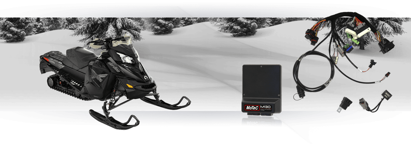
MoTeC's M130 Ski-Doo 1200XS 2016 kit is designed as a complete replacement for the factory-fitted ECU, delivering plug-in convenience with fully programmable control.

The kit uses existing wiring, sensors and hardware and all essential original functions are maintained.

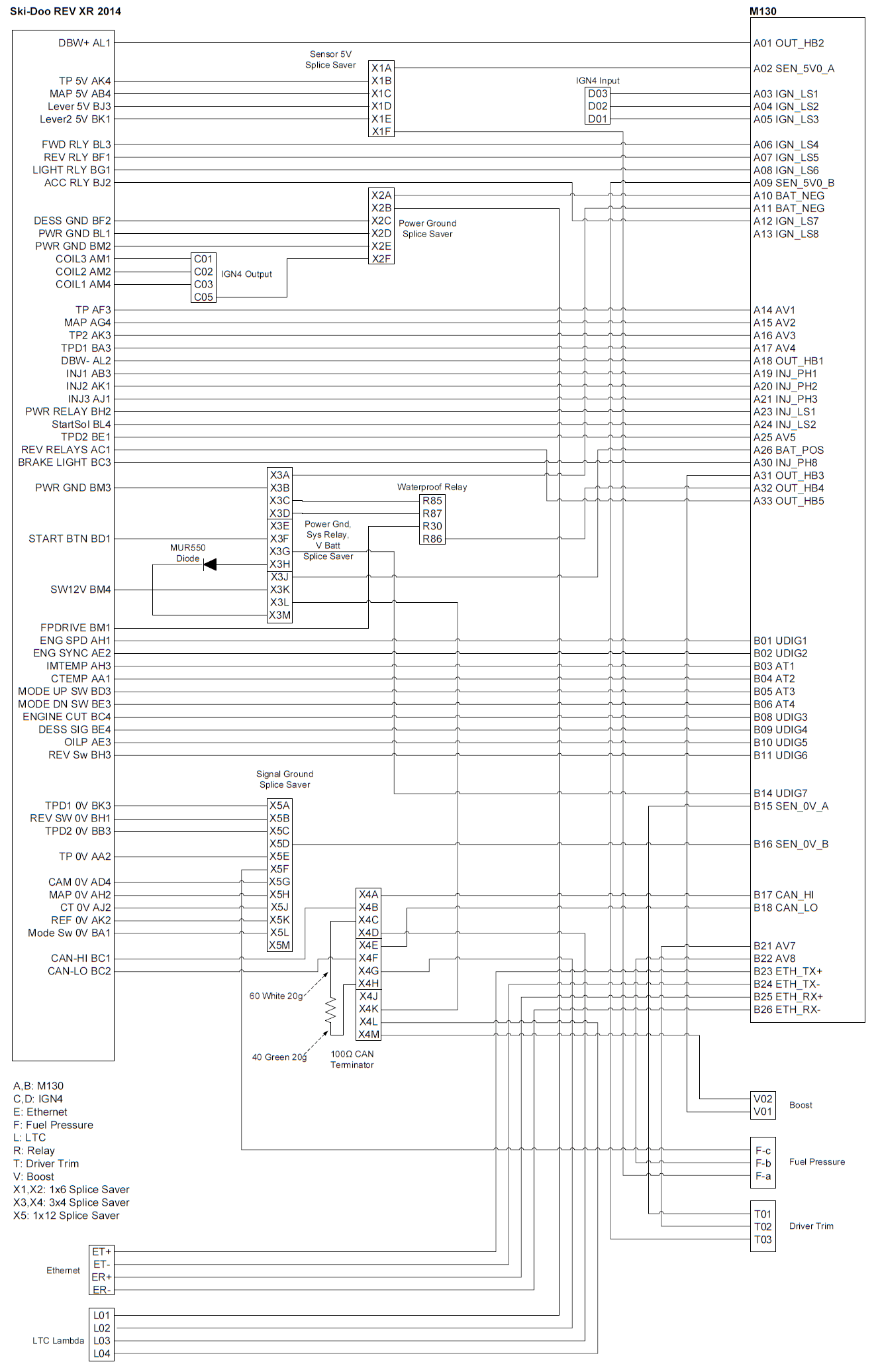
The M1 ECU with the dedicated firmware package loaded, provides the functionality of MoTeC's GPA Package with additional features uniquely catered to these snowmobiles. This product includes CAN messaging for full OE vehicle integration.

KIT CONTENTS

  • 13130M - M130 ECU MARINE

OR

  • 13150M - M150 ECU MARINE

Preloaded with the corresponding Ski-Doo Snowmobile M1 Package.

  • 61281 - SKIDOO REV-XR 2014 M130 ADAPTOR LOOM
  • 41212 - IGN4 IGNITION MODULE - 4 CHANNEL
  • 61406 - RELAY WATER PROOF
Licence
  • 23047 - M1 LICENCE - SNOW MOBILE

This Licence is required to run the Package in the ECU.

FEATURES

  • This kit fully integrates with these original systems
    • start system
    • reverse
    • emergency stop
    • lanyard stop
    • dash functionality
    More detailed information on specific kit functionality in the Installation notes section.
  • For ease of integration a number of features are pre-configured to suit compatible vehicles
    • Sensor calibrations for Original Equipment (OE) sensors and engine triggers.
    • Control of primary (Port Injector) fuel system.
    • Reference mode for engine synchronisation.
    • Physical settings for engine displacement, fuel density, stoichiometric ratio, fuel pressure, and primary injector linearisation, which allow for simplified engine start-up prior to tuning.
    • CAN messaging for OE systems including dashboard.
    • Transient fuelling compensation using physical modelling of fuel film for port injectors.
    • Track speed detection sent to OE dash via CAN.
    • On-board knock control for each cylinder using the OE knock sensor (optionally can be configured to use up to 2 sensors) and selectable centre frequency.
    • Idle closed loop control system using ignition and Idle control valve actuation.
    • Engine Load Average channel with tables for engine speed limit, ignition timing trim, fuel mixture aim, boost limit, and throttle limit.
  • GPA configurable features
    • Configurable boost control with single wastegate actuator. Single and dual solenoids supported.
    • Configurable security for multiple users with differing access options.
    • Configurable closed loop alternator system for PWM field winding control.
    • Intercooler temperature and spray control.
    • Traction control with tables for aim main, aim compensation, control range
  • Included GPR features
    • Lap distance, time and number via BR2 or switched input, with split and sector options.
    • Vehicle speed limiting (pit speed control).
    • Race time system with tables for ignition timing trim, fuel mixture aim, boost limit, and throttle limit.
    • Configurable anti-lag for single turbo variants with ignition timing limit, fuel volume trim, ignition cut, fuel cut, engine speed limit, boost aim and throttle aim tables.
    • Configurable launch control with tables.
    • Optionally configurable secondary (Port Injector) fuel control with a tuneable balance table.
  • Additonal optional integrations
    • Support of MoTeC devices: ADR, E8XX, PDM, SLM, VCS.
    • 8 configurable driver switches and 8 rotary switches each with 9 positions that can be simultaneously mapped to launch control, pit switch, anti-lag, traction, race time reset, engine speed limit maximum, throttle lever translation, fuel volume trim, ignition timing, fuel mixture aim, boost limit, traction aim, and traction control range.
    • Lambda control is supported with optional LTC and Bosch LSU4.9 sensor
    • GPS acquisition and logging via CAN or RS232.
    • ECU CAN Receive from a defined ID base address for data reception from MoTeC devices.
    • Coolant pump output with PWM control.
    • Coolant pump after-run functionality, optionally with additional pump output.
    • Switchable inlet manifold runner with position feedback.
    • Engine run time total for engine hour logging.
    • Pulsed tachometer output with configurable output pin and scaling.
    • Transmission pump output with transmission temperature threshold and hysteresis control.
    • Optional channels for additional sensors via input pin and/or CAN message, including:
      • Airbox Mass Flow, Temperature and Pressure
      • Ambient Temperature
      • Brake Pressure
      • Brake Switch
      • Coolant Pressure and Temperature
      • Engine Oil Temperature
      • Engine Crankcase Pressure
      • Exhaust Pressure
      • Exhaust Temperature (EGT) via TCA Thermocouple Amplifier, Generic CAN, or E888 for Collector and Cylinders 1 to 3.
      • Exhaust Lambda via LTC, LTCN, or PLM for Collector and Cylinders 1 to 3.
      • Fuel Pressure and Temperature
      • Intercooler Temperature
      • Steering Angle
      • Transmission Temperature
      • Turbocharger Speed
      • G-Force (acceleration) - Longitudinal, Lateral, Vertical

INSTALLATION NOTES

Mode Switching

The Mode Up and Mode Down buttons may be used in a number of ways to control vehicle functions. The M1 Package settings allow for the mode values zero and one to control Engine Speed Limit Maximum, Throttle Lever Translation, Ignition Timing, Fuel Mixture Aim, and Engine Boost Limit according to the table.

Mode Switch Zero One
Engine Speed Limit 8850 8800
Throttle Lever Translation Full throttle range Reduced throttle range (60%)
Ignition Timing Main Timing Map A Timing Map B
Fuel Mixture Aim Trim 0% -3%
Engine Boost Limit 100% -60%
Power Switching, Emergency Stop, and Lanyard

Vehicle power is switched on by connecting the lanyard (named Tether Cord or Engine Cut-Off Switch in OE manuals) and pressing the start button.

The start button provides temporary power to the M1 ECU which then turns on the ECU power relay.

The ECU power relay will remain turned on depending on the engine run state and the lanyard, along with M1 Package settings which may be adjusted to suit.

Some Tune operations require an ECU reset. See Maintaining M1 ECU power when sending Packages.

If the Emergency Engine Stop switch is in the On position (pulled up) the engine will crank and start when the start button is pressed.

When the engine is running, removing the lanyard or pushing down the emergency engine stop switch will stop the engine. Power to the ECU is maintained depending on the M1 Package settings:

The Ski-Doo Lanyard Power Hold Mode determines when the ECU powers off after the engine stops. Holding power can be beneficial in race conditions so the ski can crank and start without the initial power up delay. In normal use, this can be undesirable because a powered ECU eventually flattens the battery.

Ski-Doo Lanyard Power Hold Mode Behaviour
Disabled ECU will power down in Power Hold Time after the engine stops.
Extended While the lanyard is connected, the ECU will power down in Lanyard Extended Power Hold Time after the engine stops.
Enabled While the lanyard is connected, the ECU will not power down .
Maintaining M1 ECU power when sending Packages

Some Tune operations require an ECU reset. In this case, the M1 ECU will turn off the ECU power relay.

M1 Tune displays an icon next to Package settings where an ECU reset is required.

In this example, changing Pullup Control or Active Edge settings will require an ECU reset, while changing Threshold or Hysteresis will not.

When saving a Package with altered settings where a reset is not required, ECU power will be maintained and no special actions are required.

When sending a complete Package, updating Firmware or system files or saving a Package where a reset is required, the ECU power relay will turn off and power will be lost. To prevent this, the start button should be used to provide temporary power to the M1 ECU.

Follow these steps to prevent power loss while the Package is send:

  1. Push the Emergency Engine Stop Switch into the Off position (down)
  2. Hold the Start button down for the entire duration of the Package send process.
  3. Once the package has been sent, release the Start Button
  4. To run the engine, pull up the Emergency Engine Stop Switch into the On position and start as normal.

PINOUT

M130 Connector A — 34 way
Mating Connector: Tyco Superseal 34 Position Keying 1 – MoTeC #65044
Pin Number Designation Full Name OE Pin Function
A01 OUT_HB2 Half Bridge Output 2 AL1 Throttle Servo Motor Output
A02 SEN_5V0_A Sensor 5.0 V A AK4, AB4, BJ3, BK1, M03
A03 IGN_LS1 Low Side Ignition 1 AM4

Ignition Cylinder 1 Output

A04 IGN_LS2 Low Side Ignition 2 AM2 Ignition Cylinder 2 Output
A05 IGN_LS3 Low Side Ignition 3 AM1 Ignition Cylinder 3 Output
A06 IGN_LS4 Low Side Ignition 4 BL3 Ski-Doo Reverse Disengage Output
A07 IGN_LS5 Low Side Ignition 5 BF1 Ski-Doo Reverse Engage Output
A08 IGN_LS6 Low Side Ignition 6 BG1 Ski-Doo Headlight Relay Output
A09 SEN_5V0_B Sensor 5.0 V B T03 5V supply for Trim Switch
A10 BAT_NEG1 Battery Negative BL1, BM2, BF2, L01, C05
A11 BAT_NEG2 Battery Negative BM3, R85, R87
A12 IGN_LS7 Low Side Ignition 7 BJ2 Ski-Doo Accessory Relay Output
A13 IGN_LS8 Low Side Ignition 8
A14 AV1 Analogue Voltage Input 1 AF3 Throttle Servo Position Sensor Main
A15 AV2 Analogue Voltage Input 2 AG4 Inlet Manifold Pressure Sensor
A16 AV3 Analogue Voltage Input 3 AK3 Throttle Servo Position Sensor Tracking
A17 AV4 Analogue Voltage Input 4 BA3 Throttle Lever Sensor Main
A18 OUT_HB1 Half Bridge Output 1 AL2 Throttle Servo Motor Output
A19 INJ_PH1 Peak Hold Injector 1 AB3 Fuel Cylinder 1 Primary Output
A20 INJ_PH2 Peak Hold Injector 2 AK1 Fuel Cylinder 2 Primary Output
A21 INJ_PH3 Peak Hold Injector 3 AJ1 Fuel Cylinder 3 Primary Output
A22 INJ_PH4 Peak Hold Injector 4
A23 INJ_LS1 Low Side Injector 1 BH2, BE4 ECU Power Relay Output
A24 INJ_LS2 Low Side Injector 2 BL4 Ski-Doo Start Relay Output
A25 AV5 Analogue Voltage Input 5 BE1 Throttle Lever Sensor Tracking
A26 BAT_POS Battery Positive BM4 ECU Battery Voltage
A27 INJ_PH5 Peak Hold Injector 5
A28 INJ_PH6 Peak Hold Injector 6
A29 INJ_PH7 Peak Hold Injector 7
A30 INJ_PH8 Peak Hold Injector 8 BC3 Brake Light Output
A31 OUT_HB3 Half Bridge Output 3 V01 Boost Actuator Output
A32 OUT_HB4 Half Bridge Output 4 BM1 Fuel Pump Output
A33 OUT_HB5 Half Bridge Output 5 AC1 Reverse Relay Output
A34 OUT_HB6 Half Bridge Output 6
M130 Connector B — 26 way
Mating Connector: Tyco Superseal 26 Position Keying 1 – MoTeC #65045
Pin Number Designation Full Name OE Pin Function
B01 UDIG1 Universal Digital Input 1 AH1 Engine Speed Sensor
B02 UDIG2 Universal Digital Input 2 AE2 Engine Synchronisation Sensor
B03 AT1 Analogue Temperature Input 1 AH3 Inlet Air Temperature Sensor
B04 AT2 Analogue Temperature Input 2 AA1 Coolant Temperature Sensor
B05 AT3 Analogue Temperature Input 3 BD3 Driver Mode Up Switch
B06 AT4 Analogue Temperature Input 4 BE3 Driver Mode Down Switch
B07 KNOCK1 Knock Input 1 Knock Sensor 1
B08 UDIG3 Universal Digital Input 3 BC4 Ski-Doo Emergency Stop Button
B09 UDIG4 Universal Digital Input 4 BC3 Ski-Doo Lanyard Switch
B10 UDIG5 Universal Digital Input 5 AE3 Engine Oil Pressure Low Switch
B11 UDIG6 Universal Digital Input 6 BH3 Ski-Doo Reverse Engaged Switch
B12 BAT_BAK Battery Backup
B13 KNOCK2 Knock Input 2 Knock Sensor 1
B14 UDIG7 Universal Digital Input 7 BD1 Ski-Doo Start Button
B15 SEN_0V_A Sensor 0V A T01
B16 SEN_0V_B Sensor 0V B BK3, BH1, BB3, M01, AA2, AD4, AH2, AJ2, AK2, BA1
B17 CAN_HI CAN Bus 1 High BC1, L03
B18 CAN_LO CAN Bus 1 Low BC2, L02
B19 SEN_6V3 Sensor 6.3V
B20 AV6 Analogue Voltage Input 6
B21 AV7 Analogue Voltage Input 7 T02 Driver Trim Switch
B22 AV8 Analogue Voltage Input 8 F02 Fuel Pressure Sensor
B23 ETH_TX+ Ethernet Transmit+ Ethernet Green/White
B24 ETH_TX- Ethernet Transmit- Ethernet Green
B25 ETH_RX+ Ethernet Receive+ Ethernet Orange/White
B26 ETH_RX- Ethernet Receive- Ethernet Orange
Adapter Loom Wiring Schematic

PURCHASING

If you are interested in purchasing this product contact an Authorised MoTeC Dealer.

PACKAGE DOWNLOAD

Download this package from MoTeC Online.

DOWNLOADS

User Manuals & Guides
Name
Version / Part
Published
Download
Name, Version / Part, Published
Name
Version / Part
Published
Download
M1 Launch Control User Guide
Mar 2017
Download
M1 Launch Control User Guide
Mar 2017
M1 Launch Control User Guide
Mar 2017
Download
M1 To PDM CAN Messaging User Guide
Aug 2017
Download
M1 To PDM CAN Messaging User Guide
Aug 2017
M1 To PDM CAN Messaging User Guide
Aug 2017
Download
Useful Links

This page shows the relevant downloads for this product. For a full selection of MoTeCs downloads visit the Downloads page.


To keep up-to-date with the latest webinars or software you can subscribe to our mailing lists and we will send you a message when new items are released.

To sign-up for a mailing list click the "SIGN-UP: WEBINAR NEWS" or "SIGN-UP: SOFTWARE RELEASE" button below.

OVERVIEW

KIT CONTENTS

FEATURES

INSTALLATION NOTES

PINOUT

PURCHASING

PACKAGE DOWNLOAD

DOWNLOADS