This Package, used with an activated MoTeC M150 ECU, is a fully programmable replacement for the factory-fitted Subaru ‘Spec’ STI 2015 ECU.
Subaru Spec STI 2015 M1 Package
Subaru Spec STI 2015 M1 Package
Subaru Spec STI 2015 M1 Package
Part No: #23202
Included are numerous ancillary features common to race cars, such as anti-lag, driver switches (pit switch, launch enable, boost limit etc.), motorsport gearbox control, knock control, intercooler sprays, launch control, gearbox coolant pumps and traction control. It also caters for many systems found on modified road vehicles that may be useful in a racing context, such as air conditioning control and five definable control outputs.
This Package seamlessly integrates with other MoTeC products and provides pre-defined CAN messaging for all current Display Loggers, Enclosed Loggers, Power Distribution Modules and other devices including E888, VCS, GPS, ADR, BR2 and SLM.
If the optional Subaru Adaptor Loom is used, no rewiring is necessary. The loom plugs into the stock wiring harness, using the original sensors and fuel system. All original functions are maintained.
The following components can be supplied together for a complete solution:
- 13150 - M150 ECU13150: M150 ECU
- 23202 - M1 LICENCE - SUBARU WRX STI 2007 EJ2xx
- 61289 - SUBARU STI 2008-10 M150 ADAPTOR LOOM
-
Fully integrates with these original systems: ABS/Brakes, SI Drive, Air Conditioning, Start via Key or Button, VDC.
Lambda control is supported with an optional LTC and Bosch LSU4.9 sensor. See
Operation for further details. - Pre-configured sensor calibrations for Original Equipment (OE) sensors and engine triggers.
- Pre-configured control of primary (Port Injector) fuel system.
- Optionally configurable secondary (Port Injector) fuel control with a tuneable balance table.
- Pre-configured single fuel operation with selectable properties.
- Optional alternative fuel operation for Flex Fuel using ethanol composition sensor, or Secondary Fuel operation on secondary injectors.
- Pre-configured reference mode for engine synchronisation.
- Pre-configured physical settings for engine displacement, fuel density, stoichiometric ratio, fuel pressure, and primary injector linearisation, which allow for simplified engine startup prior to tuning.
- Pre-configured CAN messaging for OE systems including dashboard, DCCD, SI Drive, ABS.
- Pre-configured control for MoTeC SDC3 (with M1-specific firmware upgrade). See
Centre Differential Control for further information. - Pre-configured control of OE coolant fan with temperature thresholds.
- Pre-configured transient fuelling compensation using physical modelling of fuel film for port injectors.
- Idle closed loop control system using ignition and drive by wire actuation.
- Pre-configured adjustable inlet manifold tumble valves with position feedback.
- Pre-configured on-board knock control for each cylinder using the OE knock sensor (optionally can be configured to use up to 2 sensors) and multiple centre frequencies.
- Pre-configured boost control with single wastegate actuator. Single and dual solenoids supported.
- Pre-configured air conditioner request and clutch control.
- Configurable anti-lag for single turbo variants with ignition timing limit, fuel volume trim, ignition cut, fuel cut, engine speed limit, boost aim and throttle aim tables.
- GPS acquisition and logging via CAN or RS232.
- Intercooler temperature and spray control.
- Lap distance, time and number via GPS, BR2 or switched input, with split and sector options.
- Support of MoTeC devices: ADR, E8XX, PDM, SLM, VCS.
- Coolant pump output with PWM control.
- Coolant pump afterrun functionality, optionally with additional pump output.
- Configurable launch control with tables.
- Configurable closed loop alternator system for PWM field winding control.
- Race time system with tables for ignition timing trim, fuel mixture aim, boost limit and throttle limit.
- Engine Load Average channel with tables for engine speed limit, ignition timing trim, fuel mixture aim, boost limit, and throttle limit.
- Engine run time total for engine hour logging.
- Configurable security for multiple users with differing access options.
- ECU CAN Receive from a defined ID base address for data reception from MoTeC devices.
- Vehicle speed limiting (pit speed control).
- 8 configurable driver switches and 8 rotary switches each with 10 positions that can be simultaneously mapped to launch control, pit switch, anti-lag, traction, race time reset, engine speed limit maximum, throttle pedal translation, fuel volume trim, ignition timing, fuel mixture aim, boost limit, traction aim, and traction control range.
- Pre-configured pulsed tachometer output with configurable output pin and scaling.
- Transmission pump output with transmission temperature threshold and hysteresis control.
- Traction control with tables for aim main, aim compensation, control range.
- Optional channels for additional sensors via input pin and/or CAN message, including:
- Airbox Mass Flow, Temperature and Pressure
- Ambient Pressure and Temperature
- Boost Pressure
- Brake Pressure Front and Rear
- Brake Switch
- Clutch Switch, Pressure and Position
- Coolant Pressure and Temperature
- Engine Oil Pressure and Temperature
- Engine Crankcase Pressure
- Exhaust Pressure
- Exhaust Temperature (EGT) via TCA Thermocouple Amplifier, Generic CAN, or E888 for Collector and Cylinders 1 to 4.
- Exhaust Lambda via LTC, LTCN, or PLM for Collector and Cylinders 1 to 4.
- Fuel Flow Supply and Return
- Fuel Pressure and Temperature
- Fuel Tank Level
- Intercooler Temperature
- Steering Angle and Pressure
- Transmission Temperature and Pressure
- Turbocharger Speed, Inlet and Outlet Temperature
- G-Force (acceleration) - Longitudinal, Lateral, Vertical
- Wastegate Pressure and Position
- Wheel Speed
When the M150 ECU is installed according to the included wiring pinout, this Package mimics most aspects of OE operation, as follows.
Starting
Starter motor operation is controlled by the M1 ECU.
STI Start Type
- Set to Key if the vehicle has a key operated starter.
In this mode the Start Relay will be turned on with ignition power until Engine Speed is above Start Engine Speed Threshold. The start relay is only to prevent cranking while the engine is running. The clutch must be pressed and key turned to the start position to crank the engine.
If this mode is incorrectly set on a push button start vehicle, the engine will crank as soon as the clutch is pressed.
- Set to Button if the vehicle has push button start.
In this mode the Start Relay will activate when the clutch and start buttons are pressed at the same time. The keyless access module in the vehicle turns on ignition power to the ECU as well as signalling the ECU to crank the engine by the pin connected to Start Request. When this happens the ECU turns on the Start Relay until the engine starts or the Start Timeout elapses.
If this mode is incorrectly set on a key start vehicle, the starter will not operate.
Alternator
The original equipment alternator on this vehicle has no interaction with the engine ECU. If a replacement alternator is used, the M1 can control the field winding to achieve the desired battery voltage.
Air Conditioning
Air conditioning requests are received from the vehicle via CAN. The M1 ECU controls the Air Conditioner Clutch Output based on the request and additional settings within the Air Conditioner group.
DCCD
See
SI Drive
The SI Drive switch on the centre console is configured as Driver Rotary Switch 2, allowing control over many features simultaneously.
Each SI Drive mode is mapped numerically:
| Position | -1 | 0 | 1 | 2 | 3 |
|---|---|---|---|---|---|
| Mode | Unknown | None | Sharp | Intelligent | Sport |
| Mapping | Nil | Nil | Two | Zero | One |
Mapping for the Unknown or None positions would have no effect on operation, while mapping for Sharp, Intelligent and Sport modes may target such features as Anti-Lag, Traction, Boost Limit or Fuel Mixture Trim.
VDC Disable Switch
The VDC Disable Switch on the centre console is configured as Driver Switch 1, allowing control over many features simultaneously.
VDC Sport Mode Switch
The VDC Sport Mode Switch on the centre console is configured as Driver Switch 2, also allowing control over many features simultaneously.
Vehicle Yaw Rate and Acceleration
These channels are received from the OE Body CAN messaging and may be logged for analysis. Vehicle Acceleration Lateral may be used as a control input for Traction Aim Compensation.
Wheel Speeds
These channels are received from the OE CAN messaging and are used in many subsystems, including Vehicle Speed, Traction Control, Gear Detection and Pit Speed Limit.
If required, OE wheel speed information may be replaced by using hard-wired wheel speed sensors and re-configuring the Wheel Speed resources.
Gear Shift
Operation is configured similarly to that of MoTeC’s M1 GPR Packages.
Two options are available for Differential Control:
- Original Equipment DCCD ECU is installed on the car.
- MoTeC SDC3-M1 ECU is installed on the car.
Configuring Original Equipment DCCD Control
When using the OE DCCD controller the only requirement for the M1 is to transmit normal CAN messaging. No user adjustment of centre differential behaviour is available.
To configure M1 operation for the OE DCCD ECU, simply set SDC3 CAN BUS to ‘Not in Use’.
Configuring SDC3-M1 Control
A new unique firmware version for the MoTeC SDC3 allows operation with M1 ECUs that have the Subaru STI 2015 EJ207.February 2016 Package installed. The physical hardware of the SDC3 is unchanged, however the new firmware is not compatible with the existing MoTeC SDC Manager application. Refer to the end of this section for SDC3 firmware upgrade information.
Operation with the M1 Package is configured solely through settings in the M1 ECU via Tune.
To configure M1 operation for the MoTeC SDC3-M1 ECU, simply set SDC3 CAN BUS to ‘CAN Bus 2’ if using the MoTeC Adaptor Loom.
The centre differential control strategy is set up and tuned in the ECU, but follows the same strategy as the standalone SDC3 module using SDC3 Manager for Subaru STI MY08 to MY12 vehicles. The SDC3 User Manual can also be used as a reference to tune the M1 control strategy.
With this method, the SDC3 Module acts as a slave or dumb device. The M1 ECU calculates the required amount of lock based on the tuning and control strategy and sends a 'Lock' amount via CAN to the SDC3. The SDC3 sends back diagnostic information only. The ECU also sends the OE DCCD CAN data to the vehicle, rather than the SDC3 module.
SDC3-M1 Firmware Upgrade
To check which firmware is loaded in the SDC3:
- Connect to the M1 ECU
- Navigate to SDC3 Internal Firmware Version
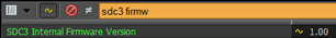
-
If the SDC3-M1 firmware is installed, SDC3 Internal Firmware Version is 1.00.

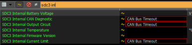
-
If the legacy V1.26 software is installed, CAN Bus Timeout will be indicated next to SDC3 Internal channels. The SDC3 firmware must be upgraded using the MoTeC SDC3 M1 Upgrade utility.
SDC3-M1 Upgrade Procedure
In the event that a standard SDC3 needs to be field-programmed to operate with the M1 installation, the firmware may be upgraded using the MoTeC SDC3 M1 Upgrade utility as follows:
-
Run the MoTeC SDC3 M1 Upgrade utility.
-
Observe the warning and remove fuses 2 and 7 (‘Combination Meter’) in the passenger compartment fuse panel.
-
Follow the other steps on screen. Select Start Upgrade and then select M1 ECU serial number and CAN Bus 2 (if the Adaptor Loom kit is used).
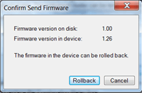
-
A prompt will indicate that the device firmware is 1.26 (legacy version). Select Rollback.
-
A progress bar will show the firmware update is in progress. Once complete, a prompt will be displayed:
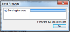
-
The M1 may now be connected in Tune and the SDC3 Internal Firmware Version observed.
SDC3-M1 CAN Messaging
The SDC3-M1 firmware operates as a slave to the M1 ECU and does not incorporate the same CAN messaging as the legacy SDC3 firmware.
The following messages may be incorporated into MoTeC dash displays:
| Channel | CAN Bus | CAN ID | Offset | Length | Values |
| SDC3 Mode | 2 | 0x380 | 1 | 1 | 1 = Open 2 = Mode 1 3 = Mode 2 4 = Mode 3 5 = Mode 4 6 = Lock |
| SDC3 Button Press | 2 | 0x164 | 0 | 1 | 0 = Up 2 = Down 4 = Mode |
| Solenoid Current Avg | 2 | 0x164 | 1 | 1 | 0.1A per bit |
| Solenoid Current Min | 2 | 0x164 | 2 | 1 | 0.1A per bit |
| Solenoid Current Max | 2 | 0x164 | 3 | 1 | 0.1A per bit |
| Solenoid Voltage + | 2 | 0x164 | 4 | 1 | 0.1V per bit |
| Solenoid Voltage - | 2 | 0x164 | 5 | 1 | 0.1V per bit |
| Output Duty Cycle | 2 | 0x164 | 6 | 2 | 0.1% per bit |
| Fault Flags | 2 | 0x165 | 0 | 1 | 1 = Open Circuit Fault 2 = Output Stuck Fault 4 = CAN diagnostic fault |
| Diagnostic Flags | 2 | 0x165 | 1 | 1 | 1 = Output Circuit Fault 2 = Current Limit Fault |
| Battery Volts | 2 | 0x165 | 2 | 2 | 0.01V per bit |
M150 Connector A - 34 Way
Mating Connector: Tyco Superseal 34 Position Keying 2 – MoTeC #65067| Pin | Designation | Full Name | OE Pin | Description |
|---|---|---|---|---|
| A01 | AT5 | Analogue Temperature Input 5 | A04 | Intake Air Temp |
| A02 | AT6 | Analogue Temperature Input 6 | B24 | Cruise Stalk |
| A03 | AV15 | Analogue Voltage Input 15 | F08 | Gear Shift Actuator Pressure (option) |
| A04 | AV16 | Analogue Voltage Input 16 | F09 | Gearbox Position (option) |
| A05 | AV17 | Analogue Voltage Input 17 | F10 | Fuel Lift Pressure (option) |
| A06 | IGN_LS9 | Low Side Ignition 9 | B14 | Sec Air Valve Relay 2 |
| A07 | IGN_LS10 | Low Side Ignition 10 | B15 | Sec Air Valve Relay 1 |
| A08 | IGN_LS11 | Low Side Ignition 11 | C08 | Sec Air Pump Relay |
| A09 | IGN_LS12 | Low Side Ignition 12 | C09 | A/C Relay |
| A10 | SEN_5V0_C1 | Sensor 5.0V C | ||
| A11 | LA_NB1 | Lambda Narrow Input 1 | ||
| A12 | LA_NB2 | Lambda Narrow Input 2 | ||
| A13 | KNOCK3 | Knock Input 3 | ||
| A14 | KNOCK4 | Knock Input 4 | ||
| A15 | DIG2 | Digital Input 2 | C33 | A/C Pressure Switch |
| A16 | DIG3 | Digital Input 3 | F06 | Gear Paddle Up Switch (option) |
| A17 | DIG4 | Digital Input 4 | F07 | Gear Paddle Down Switch (option) |
| A18 | SEN_5V0_C2 | Sensor 5.0V C | G04 | GPS 5 V Supply |
| A19 | SEN_5V0_B2 | Sensor 5.0V B | B21, B22 | |
| A20 | LIN | LIN Bus | ||
| A21 | RS232_RX | RS232 Receive | G02 | GPS Receive |
| A22 | RS232_TX | RS232 Transmit | ||
| A23 | DIG1 | Digital Input 1 | C31 | Neutral Pos Switch |
| A24 | BAT_NEG3 | Battery Negative | D02 | Ground |
| A25 | BAT_NEG4 | Battery Negative | D01 | Ground |
| A26 | SEN_0V_C1 | Sensor 0V C | F01 | Gear Shift Sensor 5V Supply (option) |
| A27 | SEN_0V_C2 | Sensor 0V C | G01 | GPS 0 V Supply |
| A28 | CAN3_HI | CAN Bus 3 High | ||
| A29 | CAN3_LO | CAN Bus 3 Low | ||
| A30 | CAN2_HI | CAN Bus 2 High | C27 | Vehicle 500 kbit/sec CAN + |
| A31 | CAN2_LO | CAN Bus 2 Low | C35 | Vehicle 500 kbit/sec CAN - |
| A32 | BAT_NEG5 | Battery Negative | D06, D26 | Ground |
| A33 | SEN_0V_B1 | Sensor 0V B | A29 | |
| A34 | SEN_0V_A1 | Sensor 0V A | A14, A24 |
M150 Connector B - 26 Way
Mating Connector: Tyco Superseal 26 Position Keying 3 – MoTeC #65068| Pin | Designation | Full Name | OE or Breakout Pin | Description |
|---|---|---|---|---|
| B01 | OUT_HB9 | Half Bridge Output 9 | D23 | Tumble Valve RH Closer |
| B02 | OUT_HB10 | Half Bridge Output 10 | D22 | Tumble Valve RH Opener |
| B03 | UDIG8 | Universal Digital Input 8 | C32 | Start Signal |
| B04 | UDIG9 | Universal Digital Input 9 | A33 | Power Steering Oil Pressure Switch |
| B05 | UDIG10 | Universal Digital Input 10 | B19 | Ignition Switch |
| B06 | UDIG11 | Universal Digital Input 11 | B20 | Brake SW1 |
| B07 | UDIG12 | Universal Digital Input 12 | B28 | Brake SW2 |
| B08 | INJ_LS5 | Low Side Injector 5 | C18 | Fan 1 Relay |
| B09 | INJ_LS3 | Low Side Injector 3 | C21 | Throttle Relay |
| B10 | AV9 | Analogue Voltage Input 9 | A27 | Secondary Air Combination Valve LH Position |
| B11 | AV10 | Analogue Voltage Input 10 | B32 | Fuel Tank Pressure |
| B12 | AV11 | Analogue Voltage Input 11 | ||
| B13 | BAT_POS2 | Battery Positive | C01 | |
| B14 | INJ_LS6 | Low Side Injector 6 | C29 | Fan 2 Relay |
| B15 | INJ_LS4 | Low Side Injector 4 | B03 | A/C Off signal |
| B16 | AV12 | Analogue Voltage Input 12 | ||
| B17 | AV13 | Analogue Voltage Input 13 | ||
| B18 | AV14 | Analogue Voltage Input 14 | ||
| B19 | BAT_POS3 | Battery Positive | C01 | Switched BAT_POS from Throttle Relay |
| B20 | OUT_HB7 | Half Bridge Output 7 | D13 | Tumble Valve LH Closer |
| B21 | OUT_HB8 | Half Bridge Output 8 | D12 | Tumble Valve LH Opener |
| B22 | INJ_PH9 | Peak Hold Injector 9 | B13 | Crank Monitor |
| B23 | INJ_PH10 | Peak Hold Injector 10 | C17 | Drain Valve |
| B24 | INJ_PH11 | Peak Hold Injector 11 | C28 | Pressure Control Solenoid |
| B25 | INJ_PH12 | Peak Hold Injector 12 | C11 | MIL Lamp |
| B26 | SEN_5V0_A2 | Sensor 5.0V A | ||
M150 Connector C - 34 Way
Mating Connector: Tyco Superseal 34 Position Keying 1 – MoTeC #65044| Pin | Designation | Full Name | OE or Breakout Pin | Description |
|---|---|---|---|---|
| C01 | OUT_HB2 | Half Bridge Output 2 | D04 | Throttle Servo Motor Output |
| C02 | SEN_5V0_A1 | Sensor 5.0V A | ||
| C03 | IGN_LS1 | Low Side Ignition 1 | D18 | Ignition Cylinder 1 Output |
| C04 | IGN_LS2 | Low Side Ignition 2 | D19 | Ignition Cylinder 2 Output |
| C05 | IGN_LS3 | Low Side Ignition 3 | D20 | Ignition Cylinder 3 Output |
| C06 | IGN_LS4 | Low Side Ignition 4 | D21 | Ignition Cylinder 4 Output |
| C07 | IGN_LS5 | Low Side Ignition 5 | D29 | Purge Solenoid 1 |
| C08 | IGN_LS6 | Low Side Ignition 6 | D27 | Wastegate Solenoid |
| C09 | SEN_5V0_B1 | Sensor 5.0V B | A19 | |
| C10 | BAT_NEG1 | Battery Negative | A05 | Ground |
| C11 | BAT_NEG2 | Battery Negative | D07 | Ground |
| C12 | IGN_LS7 | Low Side Ignition 7 | C12 | Fuel Pump Control |
| C13 | IGN_LS8 | Low Side Ignition 8 | C22 | Tachometer |
| C14 | AV1 | Analogue Voltage Input 1 | B23 | Throttle Pedal Sensor Main |
| C15 | AV2 | Analogue Voltage Input 2 | B31 | Throttle Pedal Sensor Tracking |
| C16 | AV3 | Analogue Voltage Input 3 | A18 | Throttle Servo Position Sensor Main |
| C17 | AV4 | Analogue Voltage Input 4 | A28 | Throttle Servo Position Sensor Tracking |
| C18 | OUT_HB1 | Half Bridge Output 1 | D05 | Throttle Servo Motor Output |
| C19 | INJ_PH1 | Peak Hold Injector 1 | D08 | Fuel Cylinder 1 Primary Output |
| C20 | INJ_PH2 | Peak Hold Injector 2 | D09 | Fuel Cylinder 2 Primary Output |
| C21 | INJ_PH3 | Peak Hold Injector 3 | D10 | Fuel Cylinder 3 Primary Output |
| C22 | INJ_PH4 | Peak Hold Injector 4 | D11 | Fuel Cylinder 4 Primary Output |
| C23 | INJ_LS1 | Low Side Injector 1 | C23 | ECU Power Relay Output |
| C24 | INJ_LS2 | Low Side Injector 2 | C20 | Start Relay Output |
| C25 | AV5 | Analogue Voltage Input 5 | A06 | Inlet Manifold Pressure Sensor |
| C26 | BAT_POS1 | Battery Positive | C01 | Switched BAT_POS from Throttle Relay |
| C27 | INJ_PH5 | Peak Hold Injector 5 | C30 | Starter Cut Relay |
| C28 | INJ_PH6 | Peak Hold Injector 6 | F03 | Gear Shift Actuator Pump (option) |
| C29 | INJ_PH7 | Peak Hold Injector 7 | F04 | Gear Shift Actuator Up (option) |
| C30 | INJ_PH8 | Peak Hold Injector 8 | F05 | Gear Shift Actuator Down (option) |
| C31 | OUT_HB3 | Half Bridge Output 3 | D14 | Inlet Cam Solenoid LH |
| C32 | OUT_HB4 | Half Bridge Output 4 | D16 | Inlet Cam Solenoid RH |
| C33 | OUT_HB5 | Half Bridge Output 5 | D30 | Exhaust Cam Solenoid LH |
| C34 | OUT_HB6 | Half Bridge Output 6 | D24 | Exhaust Cam Solenoid RH |
M150 Connector D - 26 Way
Mating Connector: Tyco Superseal 26 Position Keying 1 – MoTeC #65045| Pin | Designation | Full Name | OE or Breakout Pin | Description |
|---|---|---|---|---|
| D01 | UDIG1 | Universal Digital Input 1 | A13 | Engine Speed Sensor |
| D02 | UDIG2 | Universal Digital Input 2 | A21 | Inlet Cam Position LH |
| D03 | AT1 | Analogue Temperature Input 1 | B18 | Inlet Air Temperature Sensor |
| D04 | AT2 | Analogue Temperature Input 2 | A34 | Coolant Temperature Sensor |
| D05 | AT3 | Analogue Temperature Input 3 | B17 | Fuel Temperature Sensor |
| D06 | AT4 | Analogue Temperature Input 4 | B12 | Driver Cruise Switch |
| D07 | KNOCK1 | Knock Input 1 | A15 | Knock Sensor 1 |
| D08 | UDIG3 | Universal Digital Input 3 | A11 | Inlet Cam Position RH |
| D09 | UDIG4 | Universal Digital Input 4 | A31 | Exhaust Cam Position LH |
| D10 | UDIG5 | Universal Digital Input 5 | A12 | Exhaust Cam Position RH |
| D11 | UDIG6 | Universal Digital Input 6 | C25 | Clutch Switch |
| D12 | BAT_BAK | Battery Backup | B05 | BAT_HOT |
| D13 | KNOCK2 | Knock Input 2 | ||
| D14 | UDIG7 | Universal Digital Input 7 | B33 | Fuel Pump Diagnostic |
| D15 | SEN_0V_A2 | Sensor 0V A | A22 | |
| D16 | SEN_0V_B2 | Sensor 0V B | B29, B30, B34, B35, C06, A25 | |
| D17 | CAN1_HI | CAN Bus 1 High | L03 | MoTeC 1 Mbit/sec CAN |
| D18 | CAN1_LO | CAN Bus 1 Low | L02 | MoTeC 1 Mbit/sec CAN |
| D19 | SEN_6V3 | Sensor 6.3V | ||
| D20 | AV6 | Analogue Voltage Input 6 | B26 | MAF Signal |
| D21 | AV7 | Analogue Voltage Input 7 | A16 | Tumble Generator Valve Position LH |
| D22 | AV8 | Analogue Voltage Input 8 | A26 | Tumble Generator Valve Position RH |
| D23 | ETH_TX+ | Ethernet Transmit+ | Ethernet Green/White | |
| D24 | ETH_TX– | Ethernet Transmit- | Ethernet Green | |
| D25 | ETH_RX+ | Ethernet Receive+ | Ethernet Orange/White | |
| D26 | ETH_RX | Ethernet Receive- | Ethernet Orange |
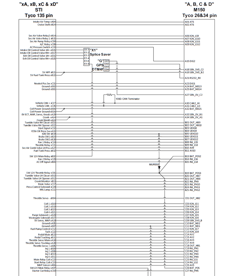
ADAPTOR LOOM WIRING SCHEMATIC PN 61289

If you are interested in purchasing this product contact an Authorised MoTeC Dealer.
Download this package from MoTeC Online.
Useful Links
This page shows the relevant downloads for this product. For a full selection of MoTeCs downloads visit the Downloads page.
To keep up-to-date with the latest webinars or software you can subscribe to our mailing lists and we will send you a message when new items are released.
To sign-up for a mailing list click the "SIGN-UP: WEBINAR NEWS" or "SIGN-UP: SOFTWARE RELEASE" button below.