The MoTeC Logo
Welcome
Products
Downloads
Training
Forum
FAQ
Careers
Dealers
Products
The MoTeC Logo
Welcome Products Downloads Training Forum FAQ Careers Dealers
The MoTeC Logo
Toyota 86 2012 FA20D Paddle Shift M1 Package
Part No: #23075

OVERVIEW

This Toyota 86 FA20D package is based on MoTeC's successful GPRP package and is available on MoTeC M150 ECUs, it is a versatile and adaptable platform for the operation of this engine.

It is configured to run the Toyota 86 FD20D Engine with the addition of a paddle shifted gearbox using switched actuators. The package allows for easy changes to engine tuning and hardware.

Along with fuel, ignition, throttle and camshaft control, this package also supports other OE ECU features, including:

  • Direct injector with high pressure fuel pumpcontrol (via OE Drive Box) and secondary port injector control(saturated high-ohm injectors only).
  • Integrates with OE ABS.
  • Full support for Cruise Control using OE controls.
  • Push Button Start.
  • Cooling Fan.
  • Air Conditioner.
  • Added support for manual air conditioner controls.
  • Power Steering.
  • Dashboard.
  • Purge Canister and Alternator control.

Included are many ancillary features common to race cars, such as driver switches (pit switch, launch enable, boost trim etc.) anti-lag, intercooler sprays, launch control and traction control.

VEHICLE COMPATIBILITY

This product includes CAN messaging for full OE vehicle integration. The Package caters for OE vehicle systems such as power steering, ABS, starting systems and dashboards.

The following table shows compatible vehicles.

Vehicle Year Engine Transmission
Toyota GT 86 2012 - 2020 FA20-H4 Manual & Automatic
Subaru BRZ 2012 - 2020 FA20-H4 Manual & Automatic
Scion FR-S 2012 - 2016 FA20-H4 Manual & Automatic

PADDLE SHIFT FEATURES

  • Paddle shift gearbox control for sequential gearboxes with switched actuators.
  • Paddle Shift Input can be hard wired or received via CAN as either up or down switches or a single linear sensor.
  • Optional lockouts for Neutral and Reverse selection.
  • Up/Down actuator control, with preload times preceding the shifts and hold time to safely engage gears.
  • Configurable Minimum/Maximum blip time on downshifts.
  • Multiple gear shift modes such as: manual, automatic, fault modes, switch selection only, disabled.
  • Closed loop gear shift strategy including retries for missed shifts.
  • Gear Shift actuator air pump support with air pressure monitoring.
  • Optional gearbox shift request via Up Shift Switch / Down Shift Switch or Gear lever Force Sensor.
  • Drive by wire throttle blip control with engine speed matching.
  • Optional throttle blip and engine speed matching when the clutch is engaged.

FEATURES

  • This package integrates with the OE (original equipment) systems of the vehicle;
    • Direct fuel injection
    • Starting systems
    • Dashboard
    • Drive Mode
    • Differential
    • Electric Power Steering
  • For ease of integration a number of features are pre-configured to suit compatible vehicles:
    • Sensor calibrations for Original Equipment (OE) sensors and engine triggers.
    • Control of primary (Direct Injector) and Secondary (port injector) fuel system.
    • Reference mode for engine synchronisation.
    • Physical settings for engine displacement, fuel density, stoichiometric ratio, fuel pressure, and injector linearisation, for simplified engine start-up prior to tuning.
    • CAN messaging for OE systems including dashboard and differential.
    • Boost control with wastegate actuator.
    • Transient fuelling compensation using physical modelling of fuel film for direct injectors.
    • On-board knock control for each cylinder using the OE knock sensors and selectable centre frequency.
    • Lambda control is supported with included LTC and Bosch LSU4.9 sensor.
    • Idle closed loop control system using ignition and throttle servo actuation.
    • Sensing of OE subsystems
      • Engine Oil Temperature and Pressure
      • Coolant Temperature
      • Boost Pressure
      • Fuel Pressure Direct and Fuel Pressure (low)
      • Transmission Temperature
      • Steering Angle, Vehicle Acceleration and Wheel Speeds
      • Airbox Mass Flow
      • Intake Manifold Pressure and Temperature
      • Clutch Position
      • Throttle Servo and Pedal Position
      • Gear Input Shaft Speed
      • Clutch
      • Brake (x2)
      • Reverse
      • Neutral
      • iMT (Downshift Blip)
      • Cruise switches
    • Control of OE subsystems:
      • Cooling Fan control
      • Airbox Flap
      • Fuel Purge Solenoid
      • Turbocharge Bypass (blowoff) Valve
      • Downshift rev matching
      • Alternator (LIN)
    • Engine Load Average channel with tables for engine speed limit, ignition timing trim, fuel mixture aim, boost limit, and throttle limit.
  • Configurable features:
    • Configurable security for multiple users with differing access options.
    • Intercooler temperature and spray control.
  • Included GPR features:
    • Lap distance, time and number via BR2 or switched input, with split and sector options.
    • Vehicle speed limiting (pit speed control).
    • Launch control
    • Race time system with tables for ignition timing trim, fuel mixture aim, boost limit, and throttle limit.
    • Configurable anti-lag with ignition timing limit, fuel volume trim, ignition cut, fuel cut, engine speed limit, boost aim and throttle aim tables.
    • Traction control with tables for aim main, aim compensation, control range
  • Additional optional integrations:
    • Support of MoTeC devices: E8XX, PDM, SLM, Keypad, Rotary Controller.
    • 8 configurable driver switches, 8 rotary switches and MoTeC Keypad and Rotary Controller support, each with 10 positions that can be simultaneously mapped to launch control, pit switch, anti-lag, traction, race time reset, engine speed limit maximum, throttle lever translation, fuel volume trim, ignition timing, fuel mixture aim, boost limit, traction aim, and traction control range.
    • GPS acquisition and logging via CAN or RS232.
    • ECU CAN Receive from a defined ID base address for data reception from MoTeC devices.
    • Coolant pump output with PWM control.
    • Coolant pump after-run functionality, optionally with additional pump output.
    • Switchable inlet manifold runner with position feedback.
    • Engine run time total for engine hour logging.
    • Pulsed tachometer output with configurable output pin and scaling.
    • Transmission pump output with transmission temperature threshold and hysteresis control.
    • Optional channels for additional sensors via input pin and/or CAN message, including:
      • Ambient Temperature
      • Brake Pressure
      • Coolant Pressure
      • Engine Crankcase Pressure
      • Exhaust Pressure
      • Temperature
      • Intercooler Temperature
      • Turbocharger Speed
      • Brake Pressure and Position
      • Coolant Pressure
      • Differential Temperature
      • Engine Crankcase Pressure
      • Exhaust Pressure and Temperature
      • Fuel Composition, Flow and Temperature
      • Transmission Pressure
      • Paddles

WIRING OPTIONS

An optional Adaptor Loom is available: 61264 – TOYOTA 86 M150 ADAPTOR LOOM.

61264 Rev A Adaptor Looms are suited to Model Year 2012-2016 only.

61264 Rev B Adaptor Looms are suited to Model Year 2012-2016 and Model year 2017+.

Model Year 2017 and later vehicles use a different Fuel Pressure Direct sensor which requires an additional wire in the adaptor loom (fitted to Rev B Adaptor Looms). If Rev A looms are used, the Fuel Pressure Direct will not be properly sensed and the car may not start.

Rev B Adaptor Looms have a label on the plastic bag which reads ‘SPU61264 TOYOTA FT86 LOOM Rev 00:00 02/10/2018’ or later date. Looms manufactured before 02/10/2018 are Rev A and not suitable for Model Year 2017 and later.

Rev B Adaptor Looms can be identified by examining the DTM12 pin breakout connector: Rev A Looms have a brown wire to pin 6; Rev B Looms do not.

Package variants on MoTeC online are named for 2012-2016 models or 2017+ models as the Fuel Pressure Direct sensor calibration and Fuel Injector Linearisation calibrations are different.

If the optional adaptor loom is used, install as follows:

  • Unplug 4 harness connectors from the OE Engine ECU (located in the passenger footwell under the glove compartment).
  • Plug the 4 harness connectors into the adaptor loom.
  • Plug the adaptor loom into the M150 ECU.
  • If GPS or LTC are supplied, plug these into the designated DTM 4 pin female plugs.
  • If other options are required, fit these to a DTM 12 pin male plug, and connect to the DTM 12 pin female plug labelled Breakout.

If the optional adaptor loom is not used, the wiring schematic in this document should be used as a reference for wiring installations. As input and output resource allocations in the M150 ECU are not fixed, the M150 ECU Package may be altered to suit other pin allocations.

Note: Some pins may provide parasitic power feeds to the M150 ECU, preventing orderly shut down. The resources allocated in this Package will not provide parasitic power feeds if used as supplied.

OPERATION

The Package mimics virtually all aspects of the OE operation as follows:

2017+ Model Update

Several changes were made for 2017+ models which must be accommodated in package settings:

Camshafts

2017 and later model employ mid-lock camshafts which have their adjustment range extended by about 20 degrees. In the case of inlet camshafts this allows the normal 42 (approximate) degrees of advance along with 20 degrees of retard. To ensure that these camshafts are in the zero position for engine start (rather than fully retarded inlet cams) a mechanical lock system secures the cam in the zero position when no control current flows through the oil solenoid. When the engine is stopped and control ceases the camshaft will 'wind down' to the mid-lock (zero) position by mechanical drag on the cam distribution system.

Whereas previous camshafts are controlled with a duty cycle range of perhaps 20 to 80%, mid-lock camshafts will return to the 'lock' position with less than perhaps 35% duty cycle. The active region of advance and retard is exercised between perhaps 40% and 90% duty cycle.

Therefore it is important to use appropriate settings for 2012-2016 or 2017+ models in the cam control groups: if the 2012-2016 settings are used with the later mid-lock cams it is possible to lose control of the cams or for them to return to the lock position when not expected. Numerous settings are critical in this regard:

Feature 2012 - 2016 models 2017+ models
Exhaust Camshaft Bank 1 / 2 Position Offset perhaps 0 to -2 degrees perhaps -16 to -18 degrees
Exhaust Camshaft Bank 1 /2 Actuator Minimum / Maximum perhaps 40% to 90% perhaps 50% to 70% (see note below about mid-lock region)
Exhaust Camshaft Bank 1 /2 Feed Forward perhaps 53.5% perhaps 59%
Inlet Camshaft Bank 1 / 2 Position Offset perhaps 1 to 2 degrees perhaps -16 to -18 degrees
Inlet Camshaft Bank 1 /2 Actuator Minimum / Maximum perhaps 30% to 90% perhaps 20% to 60% (see note below about mid-lock region)
Inlet Camshaft Bank 1 /2 Feed Forward perhaps 49% perhaps 42%

Note: Actuator Minimum / Maximum duty cycle values refer to the Control value limit before the output polarity is calculated. Therefore for an inlet camshaft with inverting polarity the mid-lock region corresponds to 0% to 35% output duty cycle, which is 65% to 100% control value (before Polarity calculation). Therefore the Actuator Maximum setting of 60% is the critical one to provide a guard-band which will prevent mid-lock operation.

For the exhaust camshafts with normal polarity the mid-lock region corresponds to 0 to 50% output duty cycle, which is 0% to 50% control value (no Polarity inversion). Therefore the Actuator Minimum setting of 50% is the critical one to provide a guard-band which will prevent mid-lock operation.

Crankshaft Rotation Sensor

2012 -2016 models use a magnetic reluctance sensor for the Crankshaft (Reference) signal. 2017+ models use a hall sensor.

Fuel Pressure Direct Pressure Sensor

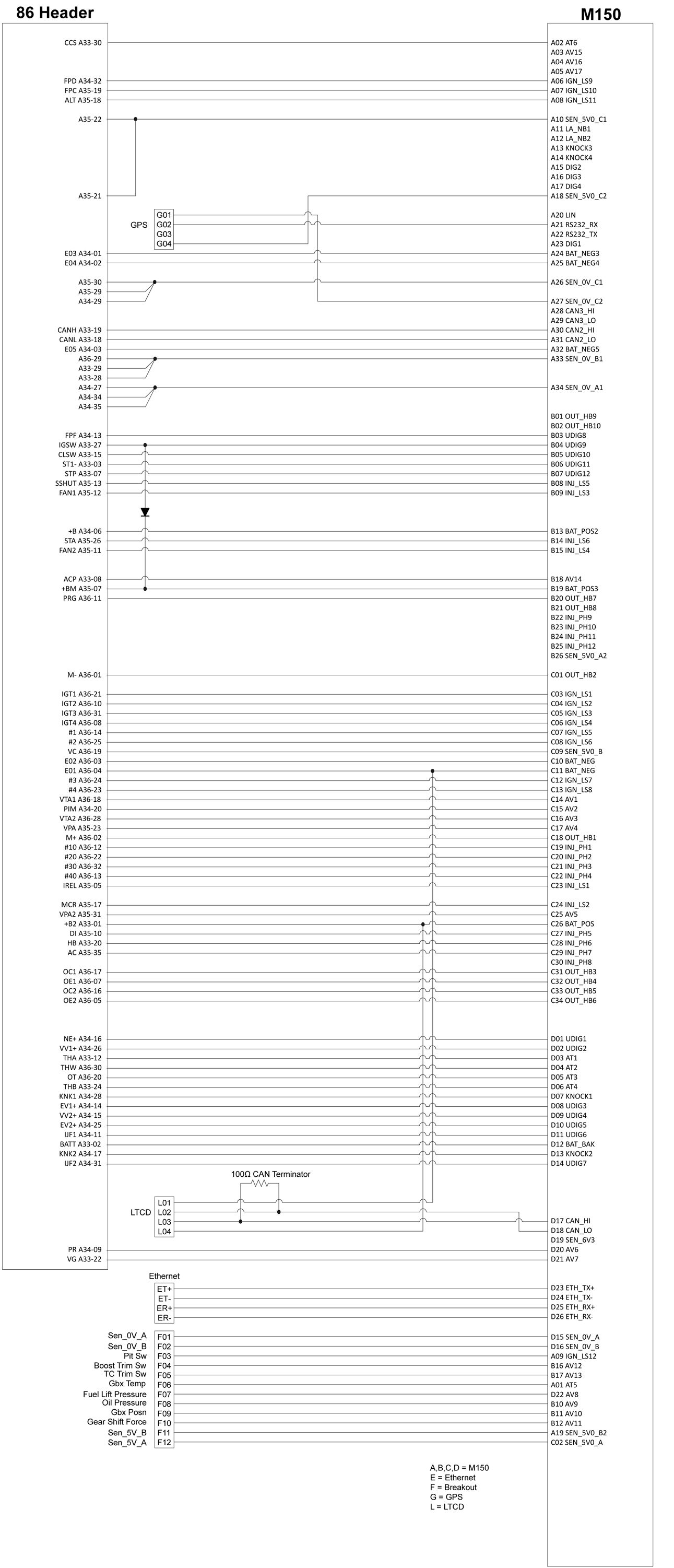
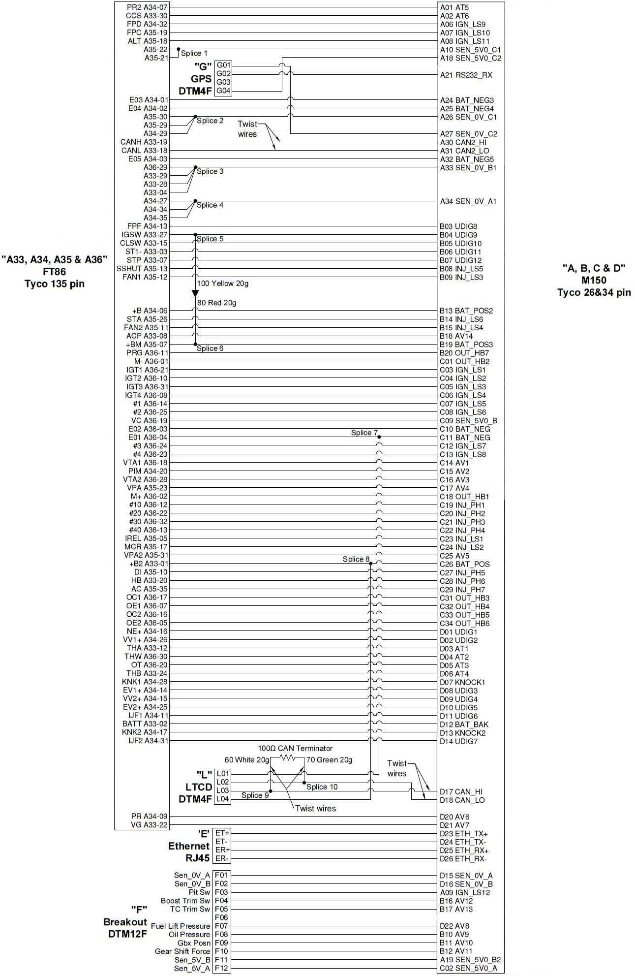
2012 - 2016 models use a single-output sensor, wired from OE Pin A34-09 to M1 pin AV6.

2017+ models use a dual-output sensor with the existing signal to AV6 covering only a small part of the overall pressure range. An additional output which covers the full range is now wired from OE pin A34-07 to M1 pin AT5. A new sensor calibration is used.

Airbox Mass Flow Sensor, Fuel Pressure Direct Pump Offset, Fuel Injector Primary Linearisation, Fuel Injector Primary Reference Flow, Fuel Injector Secondary Contribution:

The calibrations for these devices are marginally different but nonetheless should be set for the according year model.

Start System

There are two variants of the vehicle starting system: conventional key start or push button start:

  • For key start vehicles, set Toyota 86 Start Type to Key. In this mode the starter solenoid relay output (STA relay) is turned on whenever engine speed is below the Engine Run Threshold.
  • For push button start vehicles, set Toyota 86 Start Type to Button. In this mode the starter solenoid relay output (STA relay) is turned on only when the Start button is pressed, and remains on until Engine State is Run.

Both systems require the clutch to be fully depressed for the start solenoid to engage.

Transmission

There are two variants of the vehicle transmission: manual or automatic.

  • For manual transmission vehicles, set Toyota 86 Transmission Type to Manual.
  • For automatic transmission vehicles, set Toyota 86 Transmission Type to Automatic. This option provides an Idle Mass Flow Feed Forward table which allows idle adjusment when the automatic transmission selection is Drive or Reverse.

These options affect the internal CAN messaging between the M1 ECU and the OE systems.

Air Conditioner

Compressor operation is requested by the OE air conditioner system (Toyota 86 Air Conditioner Request). The M1 ECU operates the compressor clutch relay (AC relay) based on the CAN request, along with configurable enable conditions for:

  • Throttle Position
  • Engine Speed
  • Refrigerant Pressure
  • Coolant Temperature
  • Ambient Temperature

All of these conditions must be met, along with the OE request, for the compressor to operate. Default settings are used for enable components which are not required.

In addition, Idle Control may be adjusted by means of the Air Conditioner Idle Aim Compensation and Air Conditioner Idle Mass Flow Feed Forward settings.

Alternator

This product mimics operation of the original alternator system.

Power Steering

No user interaction or settings are required.

Purge Canister

A simplified purge strategy is used. Purge solenoid flow has been characterised for the OE installation and the Fuel Purge Solenoid Flow and Fuel Purge Solenoid Flow Inverse tables should not be altered.

ABS/VSC

While this product uses some sensor information provided by these systems (for example Wheel Speeds), no further interaction occurs.

Any operation of these systems that does not require engine ECU interaction (for example VSC Disable Switch) will function normally.

Allows mapping of the VSC Disable Switch and the VSC Sport Mode Switch into the M1 traction system. Refer to the help in the Package for 'Toyota 86 VSC Disable Switch'.

Fuel System

This product mimics operation of the original fuel system:

  • Primary Fuel System (Direct Injection) — this product controls the direct injectors and high pressure fuel pump by means of the OE drive box. As direct injectors are usually highly engineered for specific engines, replacing the OE direct injectors is not recommended. The OE direct injectors have a flow rate of 750 cc/min at 10 MPa and under normal operation do not exceed 40% duty cycle.

    The OE direct injection fuel pump has been characterised and settings in the Fuel Pressure Direct group should not require adjustment.

  • Secondary Fuel System (Port Injection) — conventional port injectors may be replaced with higher flow variants (for example ID1300) and injector linearisation, reference flow, and reference pressure settings should be changed to suit.
  • Fuel Pump — this product mimics low pressure (lift) pump operation. Two control signals are used: an enable and a variable duty cycle (proportional) signal.

Balance between primary (direct) and secondary (port) injection is controlled by the Fuel Injector Secondary Contribution Main table. The Fuel Injector Secondary Contribution value may be overridden if the primary fuel system fails, in which case 100% port injection is used.

Note: Lambda control is supported with optional LTC and Bosch LSU4.9 sensor.

M150 86 PINOUT

M150 Connector A – 34 Way

Note: Pin A01 functionality differs between Rev A and Rev B variants, as detailed below.

Pin Number Designation Full Name OE Pin Function
A01 Rev A Only AT5 Analogue Temperature Input 5 F06 Gearbox Temperature - optional

(2012-2016 models)

A01 Rev B Only AT5 Analogue Temperature Input 5 A34-7 Fuel Pressure Direct Bank 2 Sensor

(2017+ Models)

A02 AT6 Analogue Temperature Input 6 A33-30 Cruise Control Switch (future option)
A03 AV15 Analogue Voltage Input 15 Not Used
A04 AV16 Analogue Voltage Input 16 Not Used
A05 AV17 Analogue Voltage Input 17 Not Used
A06 IGN_LS9 Low Side Ignition 9 A34-32 Fuel Pressure Direct Bank 2 Pump A Output
A07 IGN_LS10 Low Side Ignition 10 A35-19 Fuel Pump Control
A08 IGN_LS11 Low Side Ignition 11 A35-18 Alternator Field Control
A09 IGN_LS12 Low Side Ignition 12 F03 Pit Switch (optional)
A10 SEN_5V0_C1 Sensor 5.0V C A35-22, A35-21 Sensor Supply Analogue
A11 LA_NB1 Lambda Narrow Input 1 Not Used
A12 LA_NB2 Lambda Narrow Input 2 Not Used
A13 KNOCK3 Knock Input 3 Not Used
A14 KNOCK4 Knock Input 4 Not Used
A15 DIG2 Digital Input 2 Not Used
A16 DIG3 Digital Input 3 Not Used
A17 DIG4 Digital Input 4 Not Used
A18 SEN_5V0_C2 Sensor 5.0V C G04 GPS Supply
A19 SEN_5V0_B2 Sensor 5.0V B F11 Sensor Supply Options Connector
A20 LIN LIN Bus Not Used
A21 RS232_RX RS232 Receive G02 GPS Receive
A22 RS232_TX RS232 Transmit Not Used
A23 DIG1 Digital Input 1 Not Used
A24 BAT_NEG3 Battery Negative A34-01 Power Ground
A25 BAT_NEG4 Battery Negative A34-02 Power Ground
A26 SEN_0V_C1 Sensor 0V C A35-20, A35-29, A34-29 Sensor Zero Volts Analogue
A27 SEN_0V_C2 Sensor 0V C G01 GPS Zero Volts
A28 CAN3_HI CAN Bus 3 High Not Used
A29 CAN3_LO CAN Bus 3 Low Not Used
A30 CAN2_HI CAN Bus 2 High A33-19 500k CAN to Vehicle
A31 CAN2_LO CAN Bus 2 Low A33-18 500k CAN to Vehicle
A32 BAT_NEG5 Battery Negative A34-03 Power Ground
A33 SEN_0V_B1 Sensor 0V B A36-29, A33-29, A33-28 Sensor Zero Volts Analogue
A34 SEN_0V_A1 Sensor 0V A A34-34, A34-27, A34-35 Sensor Zero Volts Analogue
M150 Connector B – 26 Way
Pin Number Designation Full Name OE Pin Function
B01 OUT_HB9 Half Bridge Output 9 Not Used
B02 OUT_HB10 Half Bridge Output 10 Not Used
B03 UDIG8 Universal Digital Input 8 Not Used Fuel Pressure Direct Pump Feedback
B04 UDIG9 Universal Digital Input 9 A33-27 Ignition Switch
B05 UDIG10 Universal Digital Input 10 A33-15 Clutch Switch
B06 UDIG11 Universal Digital Input 11 Normal Open Stop Switch Brake Lights
B07 UDIG12 Universal Digital Input 12 Normal Closed Stop Switch Brake Lights
B08 INJ_LS5 Low Side Injector 5 A35-13 SSHUT EFI Relays
B09 INJ_LS3 Low Side Injector 3 A35-12 FAN1
B10 AV9 Analogue Voltage Input 9 F08 Oil Pressure (optional)
B11 AV10 Analogue Voltage Input 10 F09 Gearbox Position (optional)
B12 AV11 Analogue Voltage Input 11 F10 Gear Shift Force (optional)
B13 BAT_POS Battery Positive A34-06 Switched Supply
B14 INJ_LS6 Low Side Injector 6 A35-26 STA Starter Relay
B15 INJ_LS4 Low Side Injector 4 A35-11 FAN2
B16 AV12 Analogue Voltage Input 12 F04 Boost Trim Switch (optional)
B17 AV13 Analogue Voltage Input 13 F05 TC Trim Switch (optional)
B18 AV14 Analogue Voltage Input 14 A33-08 ACP Air Conditioner Refrigerant Switch
B19 BAT_POS Battery Positive A35-07 Switched Supply
B20 OUT_HB7 Half Bridge Output 7 A36-11 Purge Solenoid
B21 OUT_HB8 Half Bridge Output 8 Not Used
B22 INJ_PH9 Peak Hold Injector 9 Not Used
B23 INJ_PH10 Peak Hold Injector 10 Not Used
B24 INJ_PH11 Peak Hold Injector 11 Not Used
B25 INJ_PH12 Peak Hold Injector 12 Not Used
B26 SEN_5V0_A Sensor 5.0V A Not Used Sensor Supply Analogue
M150 Connector C – 34 Way
Pin Number Designation Full Name OE Pin Function
C01 OUT_HB2 Half Bridge Output 2 A36-01 Throttle Servo Motor
C02 SEN_5V0_A Sensor 5.0V A F12 Sensor Supply Options Connector
C03 IGN_LS1 Low Side Ignition 1 A36-21 Ignition.Cylinder 1.Output
C04 IGN_LS2 Low Side Ignition 2 A36-10 Ignition.Cylinder 2.Output
C05 IGN_LS3 Low Side Ignition 3 A36-31 Ignition.Cylinder 3.Output
C06 IGN_LS4 Low Side Ignition 4 A36-08 Ignition.Cylinder 4.Output
C07 IGN_LS5 Low Side Ignition 5 A36-14 #1 Direct Injector
C08 IGN_LS6 Low Side Ignition 6 A36-25 #2 Direct Injector
C09 SEN_5V0_B Sensor 5.0V B A36-19 Sensor Supply Analogue
C10 BAT_NEG1 Battery Negative A36-03 Power Ground
C11 BAT_NEG2 Battery Negative A36-04, L01 Power Ground, LTC Ground
C12 IGN_LS7 Low Side Ignition 7 A36-24 #3 Direct Injector
C13 IGN_LS8 Low Side Ignition 8 A36-23 #4 Direct Injector
C14 AV1 Analogue Voltage Input 1 A36-18 VTA1 Throttle Servo Position Main
C15 AV2 Analogue Voltage Input 2 A34-20 PIM Inlet Manifold Pressure
C16 AV3 Analogue Voltage Input 3 A36-28 VTA2 Throttle Servo Position Tracking
C17 AV4 Analogue Voltage Input 4 A35-23 VPA Throttle Pedal Main
C18 OUT_HB1 Half Bridge Output 1 A36-02 Throttle Servo Motor +
C19 INJ_PH1 Peak Hold Injector 1 A36-12 #10 Port Injector
C20 INJ_PH2 Peak Hold Injector 2 A36-22 #20 Port Injector
C21 INJ_PH3 Peak Hold Injector 3 A36-32 #30 Port Injector
C22 INJ_PH4 Peak Hold Injector 4 A36-13 #40 Port Injector
C23 INJ_LS1 Low Side Injector 1 A35-05 Ignition Relay
C24 INJ_LS2 Low Side Injector 2 A35-17 DBW Relay
C25 AV5 Analogue Voltage Input 5 A35-31 VPA2 Throttle Pedal Tracking
C26 BAT_POS Battery Positive A33-01 Switched Supply
C27 INJ_PH5 Peak Hold Injector 5 A35-10 DI Fuel Pump Enable
C28 INJ_PH6 Peak Hold Injector 6 A33-20 HB Blower Motor Relay
C29 INJ_PH7 Peak Hold Injector 7 A35-35 AC Air Conditioner Heater Relay
C30 INJ_PH8 Peak Hold Injector 8 Not Used
C31 OUT_HB3 Half Bridge Output 3 A36-17 OC1 Inlet Camshaft Bank 1 Actuator
C32 OUT_HB4 Half Bridge Output 4 A36-07 OE1 Exhaust Camshaft Bank 1 Actuator
C33 OUT_HB5 Half Bridge Output 5 A36-16 OC2 Inlet Camshaft Bank 2 Actuator
C34 OUT_HB6 Half Bridge Output 6 A36-05 OE2 Exhaust Camshaft Bank 2 Actuator
M150 Connector D – 26 Way
Pin Number Designation Full Name OE Pin Function
D01 UDIG1 Universal Digital Input 1 A34-16 NE+ Engine Speed
D02 UDIG2 Universal Digital Input 2 A34-26 VV1+ Inlet Camshaft Bank 1 Position
D03 AT1 Analogue Temperature Input 1 A33-12 THA Inlet Manifold Temperature
D04 AT2 Analogue Temperature Input 2 A36-30 THW Coolant Temperature
D05 AT3 Analogue Temperature Input 3 A36-20 OT Engine Oil Temperature
D06 AT4 Analogue Temperature Input 4 A33-24 THB Battery Temperature
D07 KNOCK1 Knock Input 1 A34-28 KNK1 Ignition Knock Sensor Bank 1
D08 UDIG3 Universal Digital Input 3 A34-14 EV1+ Exhaust Camshaft Bank 1 Position
D09 UDIG4 Universal Digital Input 4 A34-15 VV2+ Inlet Camshaft Bank 2 Position
D10 UDIG5 Universal Digital Input 5 A34-25 EV2+ Exhaust Camshaft Bank 1 Position
D11 UDIG6 Universal Digital Input 6 A34-11 Injector Feedback 1
D12 BAT_BAK Battery Backup A33-02 Keep Alive Memory Power
D13 KNOCK2 Knock Input 2 A34-17 KNK2 Ignition Knock Sensor Bank 2
D14 UDIG7 Universal Digital Input 7 A34-31 Injector Feedback 2
D15 SEN_0V_A Sensor 0V A F01 Sensor Zero Volts Options Connector
D16 SEN_0V_B Sensor 0V B F02 Sensor Zero Volts Options Connector
D17 CAN1_HI CAN Bus 1 High L03 1M CAN Bus to LTC
D18 CAN1_LO CAN Bus 1 Low L02 1M CAN Bus to LTC
D19 SEN_6V3 Sensor 6.3V Internal Use
D20 AV6 Analogue Voltage Input 6 A34-09 Fuel Rail Pressure (2012-2016 models)
D21 AV7 Analogue Voltage Input 7 A33-22 VG Mass Air Flow
D22 AV8 Analogue Voltage Input 8 F07 Fuel Lift Pressure (optional)
D23 ETH_TX+ Ethernet Transmit+ Ethernet Green/White
D24 ETH_TX- Ethernet Transmit- Ethernet Green
D25 ETH_RX+ Ethernet Receive+ Ethernet Orange/White
D26 ETH_RX- Ethernet Receive- Ethernet
M150 Breakout Connector F – 12 Way

Note: Pin F06 applies only to Rev A Loom variants.

Pin Number Designation Full Name M150 Pin Function
F01 SEN_0V_A Sensor 0V A D15
F02 SEN_0V_B Sensor 0V B D16
F03 IGN_LS12 Low Side Ignition 12 A09 Pit Switch
F04 AV12 Analogue Voltage Input 12 B16 Boost Trim Switch
F05 AV13 Analogue Voltage Input 13 B17 TC Trim Switch
F06 Rev A Only AT5 Analogue Temperature Input 5 A01 Gearbox Temperature (2012-2016 models)
F07 AV8 Analogue Voltage Input 8 D22 Fuel Lift Pressure
F08 AV9 Analogue Voltage Input 9 B10 Oil Pressure
F09 AV10 Analogue Voltage Input 10 B11 Gearbox Position
F10 AV11 Analogue Voltage Input 11 B12 Gear Shift Force
F11 SEN_5V0_B2 Sensor 5.0V B2 A19
F12 SEN_5V0_A Sensor 5.0V A C02

WIRING SCHEMATIC – FEBRUARY 2014 - REVISION A

WIRING SCHEMATIC - REVISION B

PURCHASING

If you are interested in purchasing this product contact an Authorised MoTeC Dealer.

PACKAGE DOWNLOAD

Download this package from MoTeC Online.

DOWNLOADS

User Manuals & Guides
Name
Version / Part
Published
Download
Name, Version / Part, Published
Name
Version / Part
Published
Download
M1 Flex Fuel User Guide
Mar 2017
Download
M1 Flex Fuel User Guide
Mar 2017
M1 Flex Fuel User Guide
Mar 2017
Download
M1 GPRP Configuration Manual
Jan 2017
Download
M1 GPRP Configuration Manual
Jan 2017
M1 GPRP Configuration Manual
Jan 2017
Download
M1 Launch Control User Guide
Mar 2017
Download
M1 Launch Control User Guide
Mar 2017
M1 Launch Control User Guide
Mar 2017
Download
M1 To PDM CAN Messaging User Guide
Aug 2017
Download
M1 To PDM CAN Messaging User Guide
Aug 2017
M1 To PDM CAN Messaging User Guide
Aug 2017
Download
Useful Links

This page shows the relevant downloads for this product. For a full selection of MoTeCs downloads visit the Downloads page.


To keep up-to-date with the latest webinars or software you can subscribe to our mailing lists and we will send you a message when new items are released.

To sign-up for a mailing list click the "SIGN-UP: WEBINAR NEWS" or "SIGN-UP: SOFTWARE RELEASE" button below.

OVERVIEW

VEHICLE COMPATIBILITY

PADDLE SHIFT FEATURES

FEATURES

WIRING OPTIONS

OPERATION

M150 86 PINOUT

WIRING SCHEMATIC – FEBRUARY 2014 - REVISION A

WIRING SCHEMATIC - REVISION B

PURCHASING

PACKAGE DOWNLOAD

DOWNLOADS