The MoTeC Logo
Welcome
Products
Downloads
Training
Forum
FAQ
Careers
Dealers
Products
The MoTeC Logo
Welcome Products Downloads Training Forum FAQ Careers Dealers
The MoTeC Logo
Toyota GR86 2022 FA24D Paddle Shift M1 Package
Image of Toyota GR86 2022 FA24D Paddle Shift M1 Package
Part No: #23775

OVERVIEW

This Toyota GR86 2022 FA24D package is based on MoTeC's GPRP-DI package and is available on the MoTeC M142 ECU. It is a versatile and adaptable platform for the operation of this engine.

It is configured to run the Toyota GR86 FA24D Engine with the addition of a paddle shifted gearbox using switched actuators. The package allows for easy changes to engine tuning and hardware.

Along with fuel, ignition, throttle and camshaft control, this package also supports other OE ECU features, including:

  • Push button start
  • Direct injector with high pressure fuel pump control and secondary port injector control (saturated high-ohm injectors only)
  • Cruise control
  • Air Conditioner Control
  • All OE dash functionality including warnings
  • ABS System integration
  • Electronic Power Steering Integration

The supplied start file contains all calibrations and settings for the sensors, direct fuel injectors, ignition coils, knock control, throttle servo, camshaft, cruise control. It also has been calibrated to match the OE factory fuelling, ignition and camshaft phasing. This saves a significant amount of time as it shortcuts the setup process.

Included are many ancillary features commonly found on race cars such as; anti-lag, driver switches (e.g. pit switch, launch enable, boost trim) gearbox control,intercooler sprays, launch control, coolant pumps and traction control

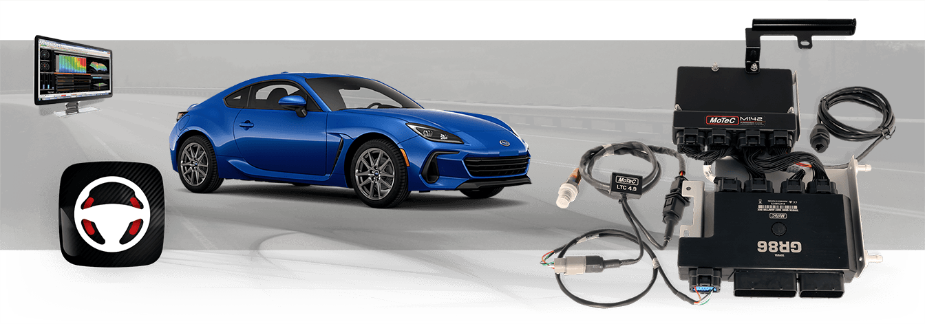
The ECU fully integrates with other MoTeC products and provides pre-defined CAN messaging for all current Display Loggers, loggers, LTCs, E888, VCS, GPS, ADR, BR2, PDM and SLM.

Drivers should be aware that specifically the following standard features do not work utilising this M1 Package: Vehicle Stability Control

As a result continuous alerts may be visible in the dash display and the following dash lights may be illuminated:

VSC (Vehicle Stability Control) Warning

VEHICLE COMPATIBILITY

The following table shows compatible vehicles.

Vehicle Year Engine Transmission
Toyota GR86 2022 FA24D Manual
Subaru BRZ 2022 FA24D Manual

This Package can be used with the Toyota GR86 2022 FA24D M1 Kit (#11413).

PADDLE SHIFT FEATURES

  • Paddle shift gearbox control for sequential gearboxes with switched actuators.
  • Paddle Shift Input can be hard wired or received via CAN as either up or down switches or a single linear sensor.
  • Optional lockouts for Neutral and Reverse selection.
  • Up/Down actuator control, with preload times preceding the shifts and hold time to safely engage gears.
  • Configurable Minimum/Maximum blip time on downshifts.
  • Multiple gear shift modes such as: manual, automatic, fault modes, switch selection only, disabled.
  • Closed loop gear shift strategy including retries for missed shifts.
  • Gear Shift actuator air pump support with air pressure monitoring.
  • Optional gearbox shift request via Up Shift Switch / Down Shift Switch or Gear lever Force Sensor.
  • Drive by wire throttle blip control with engine speed matching.
  • Optional throttle blip and engine speed matching when the clutch is engaged.

FEATURES

  • This package fully integrates with these original systems:
    • Push button Start
    • Direct fuel injection
    • Starting systems
    • Dashboard
    • Electric Power Steering
    • Variable Speed Fan Control
    • Alternator Control
    • ABS
  • For ease of integration a number of features are pre-configured to suit compatible vehicles:
    • Sensor calibrations for Original Equipment (OE) sensors and engine triggers.
    • Control of primary (Direct Injector) and Secondary (port injector) fuel system.
    • Reference mode for engine synchronisation.
    • Physical settings for engine displacement, fuel density, stoichiometric ratio, fuel pressure, and injector linearisation, for simplified engine start-up prior to tuning.
    • CAN messaging for OE systems including dashboard.
    • Transient fuelling compensation using physical modelling of fuel film for direct injectors.
    • On-board knock control for each cylinder using the OE knock sensors and selectable centre frequency.
    • Lambda control is supported with the optional LTC and Bosch LSU4.9 sensor.
    • Idle closed loop control system using ignition and throttle servo actuation.
    • Sensing of OE subsystems
      • Air Conditioning Request
      • Brake Switch
      • Brake Pressure
      • Coolant Temperature
      • Clutch Switch
      • Cruise switches
      • Engine Oil Temperature
      • Fuel Pressure Direct
      • Fuel Tank Level
      • Gear Estimate
      • Inlet Air Temperature
      • Intake Manifold Pressure
      • Lateral Acceleration
      • Longitudinal Acceleration
      • Mass Air Flow
      • Neutral Switch
      • Reverse Switch
      • Steering Angle
      • Throttle Servo and Pedal Position
      • Wheel Speeds
    • Control of OE subsystems:
      • Alternator (LIN) Control
      • Cooling Fan control
      • High Pressure Fuel Pump
      • Fuel Purge Solenoid
  • Configurable features:
    • Configurable security for multiple users with differing access options.
  • Included GPR features:
    • 5 Auxiliary Outputs for PWM Control of added actuators
      • Duty Cycles tables using Engine Speed and Throttle or Manifold Pressure Axis.
      • Activation based on Inlet Manifold Pressure or throttle position
      • Auxiliary Output 1 includes tables for Ignition Timing Compensation, Fuel Volume Trim and Mixture Trim.
    • Configurable anti-lag for single turbo with ignition timing limit, fuel volume trim, ignition cut, engine speed limit, boost aim and throttle aim tables.
    • Configurable Boost Control with single wastegate actuator. Single or dual solenoids supported
    • Coolant pump output with PWM control
    • Coolant pump after-run functionality, optionally with additional pump output.
    • Configurable Launch Control with tables with engine speed, throttle limit, boost aim and fuel volume trim.
    • Differential Temperature
    • Differential Pump output with differential temperature threshold and hysteresis control.
    • Engine Load Average channel with tables for engine speed limit, ignition timing trim, fuel mixture aim, boost limit, and throttle limit.
    • Engine Speed Limiting with Ignition Cut and/or fuel cut
    • Engine run time total for engine hour logging.
    • Exhaust Pressure
    • Exhaust Temperature
    • GPS acquisition and logging via CAN or RS232.
    • Intercooler temperature and spray control.
    • Lap distance, time and number via BR2 or switched input, with split and sector options.
    • Launch control
    • Optional alternative fuel operation for Flex Fuel using ethanol composition sensor, or Secondary Fuel operation on secondary injectors.
    • Race time system with tables for ignition timing trim, fuel mixture aim, boost limit, and throttle limit.
    • Nitrous System with two activation stages and additional fuel pumps, bottle heater and pressure sensor
    • Test settings for most outputs, including injection and ignition outputs.
    • Traction control with tables for aim main, aim compensation, control range
    • Transmission Brake control ('bump') functionality for perfect positioning of vehicles.
    • Transmission Temperature
    • Transmission pump output with transmission temperature threshold and hysteresis control.
    • Support for analogue and digital (frequency or duty cycle) sensors.
    • Vehicle speed limiting (pit speed control).
  • Additional optional integrations:
    • Support of MoTeC devices: E8XX, PDM, SLM, Keypad, Rotary Controller.
    • 8 configurable driver switches, 8 rotary switches and MoTeC Keypad and Rotary Controller support, each with 10 positions that can be simultaneously mapped to launch control, pit switch, anti-lag, traction, race time reset, engine speed limit maximum, throttle lever translation, fuel volume trim, ignition timing, fuel mixture aim, boost limit, traction aim, and traction control range.
    • ECU CAN Receive from a defined ID base address for data reception from MoTeC devices.
    • Switchable inlet manifold runner with position feedback.
    • Pulsed tachometer output with configurable output pin and scaling.
    • Optional channels for additional sensors via input pin and/or CAN message, including:
      • Ambient Temperature
      • Coolant Pressure
      • Engine Crankcase Pressure
      • Exhaust Pressure
      • Exhaust Temperature
      • Brake Position
      • Differential Temperature
      • Fuel Composition
      • Fuel Flow
      • Fuel Temperature
      • Transmission Pressure
      • Turbocharger Speed
      • Turbocharger Inlet/Outlet Temperature
      • Turbocharger Wastegate Position.

OPERATION

Reference Mode

The M1 Reference Mode in this Package is locked to the Subaru FA24D pattern

ECU Power

The M1 ECU will be powered as follows:

  • When the push start button is pushed once.
  • When the M1 is connected to the M1 Tune application via Ethernet. Once on, power will remain when the M1 is connected to the M1 Tune application via Ethernet.
Engine Start

This feature operates identically to OE behaviour.

Air Conditioning

Compressor operation is requested by the OE air conditioner system (Toyota GR86 Air Conditioner Request). The M1 ECU operates the compressor clutch relay (AC Relay) based on the CAN request along with configurable enable conditions for;

  • Throttle Position
  • Engine Speed
  • Refrigerant Pressure
  • Coolant Temperature
  • Ambient Temperature

M142 ECU PINOUT

M142 Connector A - 34 Way
Mating Connector: Tyco Superseal 34 Position Keying 2 – MoTeC #65067
Pin Designation Full Name OE or Breakout Pin Description
A01 AT5 Analogue Temperature Input 5 B1-034 Coolant Temperature Sensor
A02 AT6 Analogue Temperature Input 6
A03 AV15 Analogue Voltage Input 15 N/A N/A
A04 AV16 Analogue Voltage Input 16 N/A N/A
A05 AV17 Analogue Voltage Input 17 N/A N/A
A06 INJ_D1A_NEG Direct Injector 1A - B1-096 Cylinder 1 Primary Injector - Negative
A07 INJ_D1A_POS Direct Injector 1A + B1-087 Cylinder 1 Primary Injector - Positive
A08 INJ_D1B_POS Direct Injector 1B + Not used - DO NOT CONNECT
A09 INJ_D1B_NEG Direct Injector 1B - Not used - DO NOT CONNECT
A10 SEN_5V0_C1 Sensor 5.0V C Sensor 5V Supply
A11 LA_NB1 Lambda Narrow Input 1 N/A N/A
A12 LA_NB2 Lambda Narrow Input 2 N/A N/A
A13 KNOCK3 Knock Input 3 B1-006 Knock Sensor Bank 2 - Positive
A14 KNOCK4 Knock Input 4 B1-019 Knock Sensor Bank 2 - Negative
A15 DIG2 Digital Input 2 N/A N/A
A16 DIG3 Digital Input 3 N/A N/A
A17 DIG4 Digital Input 4 N/A N/A
A18 SEN_5V0_C2 Sensor 5.0V C
A19 SEN_5V0_B2 Sensor 5.0V B
A20 LIN LIN Bus A5-017 LIN Comms - LIN Command to Alternator
A21 RS232_RX RS232 Receive
A22 RS232_TX RS232 Transmit
A23 DIG1 Digital Input 1 N/A N/A
A24 BAT_NEG3 Battery Negative A5-071 Chassis Ground
A25 BAT_NEG4 Battery Negative A5-072 Chassis Ground
A26 SEN_0V_C1 Sensor 0V C Sensor 0V Supply
A27 SEN_0V_C2 Sensor 0V C
A28 CAN3_HI CAN Bus 3 High A5-004 CAN Bus 2 High - Vehicle 500Kbit/sec
A29 CAN3_LO CAN Bus 3 Low A5-015 CAN Bus 2 Low - Vehicle 500Kbit/sec
A30 CAN2_HI CAN Bus 2 High A5-003 CAN Bus 1 High - Vehicle 500 Kbit/sec CAN
A31 CAN2_LO CAN Bus 2 Low A5-014 CAN Bus 1 Low - Vehicle 500 Kbit/sec CAN
A32 BAT_NEG5 Battery Negative A5-069 Chassis Ground
A33 SEN_0V_B1 Sensor 0V B A5-050, A5-051, A5-065, B1-016, B1-058, B1-068, Sensor 0V Supply
A34 SEN_0V_A1 Sensor 0V A A5-055, B1-030, B1-044, B1-051 Sensor 0V Supply
M142 Connector B - 26 Way
Mating Connector: Tyco Superseal 26 Position Keying 3 – MoTeC #65068
Pin Designation Full Name OE or Breakout Pin Description
B01 OUT_HB9 Half Bridge Output 9 B1-099 Camshaft Actuator Bank 1 Intake- Negative
B02 OUT_HB10 Half Bridge Output 10 B1-108 Camshaft Actuator Bank 1 Positive - Negative
B03 UDIG8 Universal Digital Input 8 A5-032 Intake Mass Air Flow Meter - Mass Flow
B04 UDIG9 Universal Digital Input 9 A5-028 Clutch Switch
B05 UDIG10 Universal Digital Input 10 A5-037 Power
B06 UDIG11 Universal Digital Input 11
B07 UDIG12 Universal Digital Input 12
B08 INJ_LS5 Low Side Injector 5 B1-098 Fuel Port Injector Cylinder 1 - Negative
B09 INJ_LS3 Low Side Injector 3 B1-107 Fuel Port Injector Cylinder 3 - Negative
B10 AV9 Analogue Voltage Input 9 Gear Position Sensor Main Resource
B11 AV10 Analogue Voltage Input 10 Gear Shift Actuator Pressure Resource
B12 AV11 Analogue Voltage Input 11
B13 BAT_POS Battery Positive A5-067 Power
B14 INJ_LS6 Low Side Injector 6 Gear Shift Actuator Up Resource
B15 INJ_LS4 Low Side Injector 4 B1-106 Fuel Port Injector Cylinder 4 - Negative
B16 AV12 Analogue Voltage Input 12
B17 AV13 Analogue Voltage Input 13 N/A N/A
B18 AV14 Analogue Voltage Input 14 N/A N/A
B19 BAT_POS Battery Positive A5-068 Power
B20 OUT_HB7 Half Bridge Output 7 B1-100 Camshaft Actuator Bank 2 Intake - Negative
B21 OUT_HB8 Half Bridge Output 8 B1-109 Camshaft Actuator Bank 2 Exhaust - Negative
B22 INJ_D2A_NEG Direct Injector 2A - B1-095 Cylinder 2 Primary Injector - Negative
B23 INJ_D2A_POS Direct Injector 2A + B1-086 Cylinder 2 Primary Injector - Positive
B24 INJ_D2B_POS Direct Injector 2B + N/A Not used - DO NOT CONNECT
B25 INJ_D2B_NEG Direct Injector 2B - N/A Not used - DO NOT CONNECT
B26 SEN_5V0_A Sensor 5.0V A Sensor 5V Supply
M142 Connector C - 34 Way
Mating Connector: Tyco Superseal 34 Position Keying 1 – MoTeC #65044
Pin Designation Full Name OE or Breakout Pin Description
C01 OUT_HB2 Half Bridge Output 2 A5-002, A5-024 Starter Relay - Signal, Start Cut Relay - Signal
C02 SEN_5V0_A Sensor 5.0V A A5-051, B1-027, B1-040 Sensor 5V Supply
C03 IGN_LS1 Low Side Ignition 1 B1-010 Ignition Cylinder 1
C04 IGN_LS2 Low Side Ignition 2 B1-011 Ignition Cylinder 2
C05 IGN_LS3 Low Side Ignition 3 B1-012 Ignition Cylinder 3
C06 IGN_LS4 Low Side Ignition 4 B1-013 Ignition Cylinder 4
C07 IGN_LS5 Low Side Ignition 5 A5-012 EFI Main Power Relay - Power
C08 IGN_LS6 Low Side Ignition 6 A5-018 Air Conditioning Relay - Signal
C09 SEN_5V0_B Sensor 5.0V B A5-052, A5-053, B1-041 Sensor 5V Supply
C10 BAT_NEG1 Battery Negative A5-070 Chassis Ground
C11 BAT_NEG2 Battery Negative Chassis Ground
C12 IGN_LS7 Low Side Ignition 7 A5-031 Fuel Pump Relay - Signal
C13 IGN_LS8 Low Side Ignition 8 Gear Shift Actuator Down Resource
C14 AV1 Analogue Voltage Input 1 A5-049 Air Conditioning Pressure Sensor
C15 AV2 Analogue Voltage Input 2 A5-064 Throttle Pedal Position Sensor - Tracking
C16 AV3 Analogue Voltage Input 3 A5-066 Throttle Pedal Position Sensor - Main
C17 AV4 Analogue Voltage Input 4 B1-029 Throttle Servo Position Sensor - Main
C18 OUT_HB1 Half Bridge Output 1 A5-021 Certification ECU - Tachometer
C19 INJ_D3A_POS Direct Injector 3A + B1-084 Cylinder 3 Primary Injector - Positive
C20 INJ_D3B_POS Direct Injector 3B + Not used - DO NOT CONNECT
C21 INJ_D4A_POS Direct Injector 4A + B1-085 Cylinder 4 Primary Injector - Positive
C22 INJ_D4B_POS Direct Injector 4B + Not used - DO NOT CONNECT
C23 INJ_LS1 Low Side Injector 1 A5-019, A5-030 Main Fan Motor & Secondary Fan Motor
C24 INJ_LS2 Low Side Injector 2 B1-097 Cylinder 2 Port Injector
C25 AV5 Analogue Voltage Input 5 B1-043 Throttle Servo Position Sensor - Tracking
C26 BAT_POS Battery Positive
C27 INJ_D3A_NEG Direct Injector 3A - B1-093 Cylinder 3 Primary Injector - Negative
C28 INJ_D3B_NEG Direct Injector 3B - Not used - DO NOT CONNECT
C29 INJ_D4A_NEG Direct Injector 4A - B1-094 Cylinder 4 Primary Injector - Negative
C30 INJ_D4B_NEG Direct Injector 4B - Not used - DO NOT CONNECT
C31 OUT_HB3 Half Bridge Output 3 B1-083 Throttle Servo Positive
C32 OUT_HB4 Half Bridge Output 4 B1-092 Throttle Servo Negative
C33 OUT_HB5 Half Bridge Output 5 B1-114 High Pressure Fuel Pump - Negative
C34 OUT_HB6 Half Bridge Output 6 B1-105 High Pressure Fuel Pump - Positive
M142 Connector D - 26 Way
Mating Connector: Tyco Superseal 26 Position Keying 1 – MoTeC #65045
Pin Designation Full Name OE or Breakout Pin Description
D01 UDIG1 Universal Digital Input 1 B1-066 Engine Speed (Crank) Sensor
D02 UDIG2 Universal Digital Input 2 B1-078 Inlet Camshaft Bank 1 Position
D03 AT1 Analogue Temperature Input 1 A5-039 Neutral Position Switch
D04 AT2 Analogue Temperature Input 2 A5-043 Intake Mass Air Flow Sensor - Temperature
D05 AT3 Analogue Temperature Input 3 A5-040 Cruise Control Switch
D06 AT4 Analogue Temperature Input 4 B1-046 Oil Temperature Sensor
D07 KNOCK1 Knock Input 1 B1-005 Knock Sensor Bank 1 - Positive
D08 UDIG3 Universal Digital Input 3 B1-065 Exhaust Camshaft Bank 1 Position
D09 UDIG4 Universal Digital Input 4 B1-077 Intake Camshaft Bank 2 Position
D10 UDIG5 Universal Digital Input 5 B1-064 Exhaust Camshaft Bank 2 Position
D11 UDIG6 Universal Digital Input 6 A5-025 Start Switch
D12 BAT_BAK Battery Backup A5-001 Power - Battery
D13 KNOCK2 Knock Input 2 B1-018 Knock Control Sensor Bank 1 - Negative
D14 UDIG7 Universal Digital Input 7
D15 SEN_0V_A Sensor 0V A Sensor 0V Supply
D16 SEN_0V_B Sensor 0V B Sensor 0V Supply
D17 CAN1_HI CAN Bus 1 High MoTeC 1 Mbit/sec CAN
D18 CAN1_LO CAN Bus 1 Low MoTeC 1 Mbit/sec CAN
D19 SEN_6V3 Sensor 6.3V
D20 AV6 Analogue Voltage Input 6 B1-050 Fuel Pressure Sensor - Signal 2
D21 AV7 Analogue Voltage Input 7 B1-056 Fuel Pressure Sensor - Signal 1
D22 AV8 Analogue Voltage Input 8 B1-069 Manifold Pressure Sensor
D23 ETH_TX+ Ethernet Transmit+
D24 ETH_TX- Ethernet Transmit-
D25 ETH_RX+ Ethernet Receive+
D26 ETH_RX- Ethernet Receive-

PURCHASING

If you are interested in purchasing this product contact an Authorised MoTeC Dealer.

PACKAGE DOWNLOAD

Download this package from MoTeC Online.

DOWNLOADS

Useful Links

This page shows the relevant downloads for this product. For a full selection of MoTeCs downloads visit the Downloads page.


To keep up-to-date with the latest webinars or software you can subscribe to our mailing lists and we will send you a message when new items are released.

To sign-up for a mailing list click the "SIGN-UP: WEBINAR NEWS" or "SIGN-UP: SOFTWARE RELEASE" button below.

OVERVIEW

VEHICLE COMPATIBILITY

PADDLE SHIFT FEATURES

FEATURES

OPERATION

M142 ECU PINOUT

PURCHASING

PACKAGE DOWNLOAD

DOWNLOADS