The MoTeC Logo
Welcome
Products
Downloads
Training
Forum
FAQ
Careers
Dealers
Products
The MoTeC Logo
Welcome Products Downloads Training Forum FAQ Careers Dealers
The MoTeC Logo
SVIM
SVIM
SVIM
Part No: #18111

OVERVIEW

The SVIM acquires data of the highest integrity for use in advanced chassis and suspension analysis. This versatile expander works in conjunction with Display Loggers C185, C187 or C1812 and Enclosed Logger L180 to facilitate the synchronised logging of high speed, high resolution inputs.

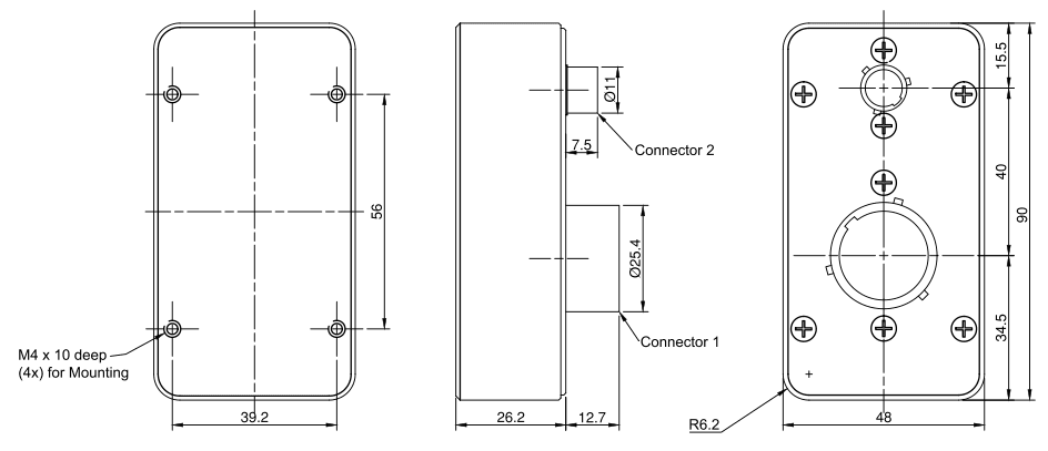
SVIMs are compact and can be located close to sensors, reducing the weight and complexity of wiring. When used in multiples, up to 200 sensor inputs are available.

FEATURES

  • Samples 18 inputs at the same instant in time using 18 separate converters with 5th order anti-aliasing filters
  • Supports many different types of sensors, including unamplified thermocouples and strain gauges
  • Configured and controlled using Dash Manager software which has special programming functions for SVIM
  • Multiple SVIMs are synchronised so every SVIM in the vehicle samples its high resolution AV inputs at the same instant in time - this is important when looking at the relationships of signals collected from different sensors around the vehicle and useful for test rigs and real time simulations

COMPATIBILITY

MoTeC Display Logger and Enclosed Logger Models
  • 18047 – L180 - LOGGER
  • 18068 – C185 - COLOUR DISPLAY LOGGER
  • 18072 – C187 - COLOUR DISPLAY LOGGER
  • 18053 – C1812 - COLOUR DISPLAY LOGGER (USB)

SPECIFICATIONS

Inputs
  • 6 x Fast analogue voltage inputs
  • 10 x High resolution analogue voltage inputs
  • 8 x High resolution differential analogue voltage inputs
  • 2 x Speed inputs
Internal sensors
  • Battery voltage
  • Internal temperature
  • Internal voltages
Communications
  • 1 x CAN
Power supply
  • Operating voltage 7 - 30 V
  • Operating current 0.22 A excluding sensor currents
  • Reverse battery protection
  • Battery transient protection
Physical
  • Case size 48 x 90 x 26.2 mm
  • Weight 150 grams
  • Ambient temperature range - 40 to 70 °C
Connectors
  • 1 x 55 pin Autosport connector
  • 1 x 5 pin Autosport connector

Input Specification
Type Qty Update rate Bits Gain Range Range Resolution Input resistance
AV F 6 5000 Hz* 12 1 0 to 5 V 1.22 mV/step 66 kΩ
AV H 10 1000 Hz 15 1-64
at Gain=1 0 to 5 V 0.153 mV/step 240 kΩ
at Gain=64 0 to 78 mV 0.00238 mV/step
AV D 8 1000 Hz 15+Sign 1-64 40 MΩ
at Gain=1 -5 to +5 mV differential 0.153 mV/step 300 kΩ differential
0 to 5 V absolute
at Gain=64 - 78 to +78 mV differential 0.00238 mV/step 2 MΩ differential
0 to 3 V absolute
AV SPD 2 100 Hz 12 1 0 to 10.3 V 2.5 mV/step 90 kΩ (Magnetic mode)
Notes:
  • Each fast AV input is sampled within 50 μsec. There is a consistent timing relationship between fast AV inputs and the other inputs.
  • All high resolution AV inputs are sampled at the same time, typically within 5 μsec ( maximum within 20 μsec)
  • For consistent phase delay all inputs must be logged at the same rate.
  • Where multiple SVIMs are used, they are all precisely synchronised so all inputs of the same type are sampled simultaneously.
  • The voltage on both inputs of the differential AV must be positive; they cannot be used to measure sensors with bipolar outputs (outputs that go positive and negative).
  • * 1000Hz when used with ADL3.

DIMENSIONS AND MOUNTING

Measurements in mm.

The product provides through holes for mounting. See drawing for details.

SOFTWARE

The SVIM has no stand-alone software package. It is configured using the Dash Manager software of the controlling Dash Logger.

  • Open the Dash Manager software
  • Select Connections > Devices
  • To add an SVIM to the devices list, select Edit > Add
  • Enter the SVIM serial number and name ad click OK
  • Assign and calibrate the various inputs to a channel
There is no need to configure the communications section; this is done automatically.

WIRING AND CONNECTING

The SVIM is powered from the vehicle battery and connected to the Data Logger via the CAN bus.

Information on CAN bus wiring can be found in the Data Logger user manual, available for download from www.motec.com.au/downloads

Please ensure wiring is according to CAN requirements and the CAN bus has at least one 100R terminating resistor.

The total available CAN bandwidth on a single CAN bus is 1 Mbit/sec. The bandwidth used by the total of all devices on the CAN bus must not exceed approximately 90% of this value (900000 bits/second)

If using multiple SVIMs and fast logging rates, it may be necessary to put some SVIMs on one CAN bus and some on the other to avoid exceeding the CAN bus bandwidth limit.

Approximate bandwidth = Total measurement rate (samples/second) x 30 (bits per sample)

The measurement rate for an input equals the logging rate or 50 Hz, whichever is higher.

The Dash Manager software will warn if the bandwidth is likely to be exceeded.

Example
  • 4 channels at 2000 Hz
  • 20 channels at 500 Hz
  • 40 channels at 20 Hz (occupies 50 Hz)

Total measurement rate (samples/sec) = 4 x 2000 + 20 x 500 + 40 x 50 = 20000

Approximate bandwidth (bits/sec) = 20000 x 30 = 600000

Maximum Sensor Currents
Battery voltage
Sensor Supply Voltage <15 V 17 V 20 V 30 V
5 V 200 mA 200 mA 200 mA 200 mA
10 V 200 mA 150 mA 100 mA 50 mA

CONNECTORS AND PINOUTS

Connector 1

55 pin Autosport connector

Mating connector: #68090

Pin Name Function
1 0V 1 Sensor 0 V 1
2 AV H1 Analogue Volt High Res 1
3 AV H2 Analogue Volt High Res 2
4 0V 4 Sensor 0 V 4
5 0V 1 Sensor 0 V 1
6 AV H3 Analogue Volt High Res 3
7 AV H4 Analogue Volt High Res 4
8 AV H5 Analogue Volt High Res 5
9 AV H6 Analogue Volt High Res 6
10 0V 4 Sensor 0 V 4
11 R1 Pull-up Resistor 1
12 R2 Pull-up Resistor 2
13 AV H7 Analogue Volt High Res 7
14 AV H8 Analogue Volt High Res 8
15 AV D1+ Analogue Volt Diff 1 +
16 AV D1- Analogue Volt Diff 1 -
17 0V 3 Sensor 0 V 3
18 5V Sensor 5 V
19 AV H9 Analogue Volt High Res 9
20 AV H10 Analogue Volt High Res 10
21 AV D8+ Analogue Volt Diff High Res 8 +
22 AV D8- Analogue Volt Diff High Res 8 -
23 AV D2+ Analogue Volt Diff High Res 2 +
24 AV D2- Analogue Volt Diff High Res 2 -
25 0V 3 Sensor 0 V 3
26 5V Sensor 5 V
27 5V Sensor 5 V
28 AV D7+ Analogue Volt Diff High Res 7 +
29 AV D7- Analogue Volt Diff High Res 7 -
30 AV D5+ Analogue Volt Differ High Res 5 +
31 AV D5- Analogue Volt Diff High Res 5 -
32 0V 2 Sensor 0 V 2
33 R3 Pull-up Resistor 3
34 R4 Pull-up Resistor 4
35 5V Sensor 5 V
36 AV D4+ Analogue Volt Diff High Res 4 +
37 AV D4- Analogue Volt Diff High Res 4 -
38 AV D6+ Analogue Volt Diff High Res 6 +
39 AV D6- Analogue Volt Diff High Res 6 -
40 0V 2 Sensor 0 V 2
41 SPD1 Speed 1
42 SPD2 Speed 2
43 5V Sensor 5 V
44 5V Sensor 5 V
45 AV D3+ Analogue Volt Diff High Res 3 +
46 AV D3- Analogue Volt Diff High Res 3 -
47 AV F1 Analogue Volt Fast 1
48 AV F2 Analogue Volt Fast 2
49 AV F3 Analogue Volt Fast 3
50 AV F4 Analogue Volt Fast 4
51 AV F5 Analogue Volt Fast 5
52 AV F6 Analogue Volt Fast 6
53 10V Sensor 10 V
54 Not Used
55 Not Used
Connector 2

5 pin Autosport connector

Mating connector: #65033

Pin Name Function
1 BAT - Battery -
2 Not Used
3 BAT + Battery +
4 CAN LO CAN Low
5 CAN HI CAN High

PRODUCT INFORMATION

Installation

IP Rating (dust or water ingress)
This product should be installed in a protected location where only occasional water splashing occurs and where the exposure to dust does not exceed conditions typical for vehicle installations.
Operating Temperature Range

This product is designed for an internal operating temperature range of -40 °C to 85 °C.

It should be installed in a location with sufficient air circulation and be shielded against thermal emissions from surrounding components.

Vibration Statement

This product is designed to withstand vibrations typical for normal vehicle installations.

It should not be exposed to severe and lasting vibrations. For example, the product should not be installed in solid connection to vibrating components like engines or undamped vehicle structures.

Safety

  • For safe operation, use only undamaged.
  • Minimal force should be exerted to plug in connectors.
  • These devices may output voltages which may constitute a risk to human safety. Appropriate precautions must be taken:
    • At no time operate the device with faulty, bare or exposed wiring.
    • Adhere to the normal supply voltage limits as listed in the Basic Specifications section.
    • Adhere to wire gauges as listed in Wiring and Connecting.

Repair

Disposal

This product should be disposed of in accordance with relevant national regulations for disposal of electronic waste. It does not contain hazardous materials which might be subject to specific materials regulations.

Manufacturer Information

MoTeC Pty. Ltd.

  • 121 Merrindale Drive, Croydon South,
  • VIC 3136, Australia.
  • Phone: +61 3 9761 5050
  • Website: www.motec.com.au
  • Email: admin@motec.com.au

PURCHASING

If you are interested in purchasing this product contact an Authorised MoTeC Dealer.

DOWNLOADS

Useful Links

This page shows the relevant downloads for this product. For a full selection of MoTeCs downloads visit the Downloads page.


To keep up-to-date with the latest webinars or software you can subscribe to our mailing lists and we will send you a message when new items are released.

To sign-up for a mailing list click the "SIGN-UP: WEBINAR NEWS" or "SIGN-UP: SOFTWARE RELEASE" button below.

OVERVIEW

FEATURES

COMPATIBILITY

SPECIFICATIONS

DIMENSIONS AND MOUNTING

SOFTWARE

WIRING AND CONNECTING

CONNECTORS AND PINOUTS

PRODUCT INFORMATION

PURCHASING

DOWNLOADS