The
Numerous supplied display layouts offer fixed graphics with configurable channels and labels, while the optional Display Creator software provides the tools for full screen customisation.
The
The
Numerous supplied display layouts offer fixed graphics with configurable channels and labels, while the optional Display Creator software provides the tools for full screen customisation.
The
IP rating is dependant upon the user ensuring that the connector entries are waterproof, which, as a minimum, requires all unused wire cavities on the connector to be plugged.
(* available via upgrades )
This pinout is suitable for cables identified as Revision: A and Revision: B on the affixed label.
| RJ45 | M122/M130/M142/M150 | CDL3/C125/C127/ C1212/L120 | |||||||
|---|---|---|---|---|---|---|---|---|---|
| Pin | Function | Revision | MoTeC Colour | Pin Numbering | M122/ M130 Pin | M142/M150 Pin | Function | Pin | Function |
| 1 | Ethernet TX+ | Rev A & Rev B | Orange-White | 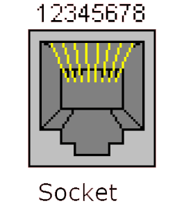 | B25 | D25 | Ethernet RX+ | 11 | Ethernet RX+ |
| 2 | Ethernet TX– | Rev A & Rev B | Orange | B26 | D26 | Ethernet RX– | 10 | Ethernet RX– | |
| 3 | Ethernet RX+ | Rev A | Green-White | B23 | D23 | Ethernet TX+ | 2 | Ethernet TX+ | |
| Rev B | Green | ||||||||
| 6 | Ethernet RX– | Rev A | Green | B24 | D24 | Ethernet TX– | 1 | Ethernet TX– | |
| Rev B | Green-White | ||||||||
The Display Logger should be connected via the CAN bus to any current MoTeC ECU and any number of other CAN devices. See the following example.

Detailed wiring information is available in the User Manual at https://www.motec.com.au/downloads
When using older MoTeC ECUs like M4/M48/M8, the Display Logger should be connected via RS232. For some ECUs, a PCI cable may also be required.
Measurements in mm.

Mating Connector: Part number 65044
| Pin | Name | Standard Function |
|---|---|---|
| 1 | E-TX– | Ethernet Transmit – |
| 2 | E-TX+ | Ethernet Transmit + |
| 3 | AV1 | Analogue Voltage Input 1 (with I/O upgrade) |
| 4 | AV2 | Analogue Voltage Input 2 (with I/O upgrade) |
| 5 | AV3 | Analogue Voltage Input 3 (with I/O upgrade) |
| 6 | AV4 | Analogue Voltage Input 4 (with I/O upgrade) |
| 7 | 8V | Sensor 8 V |
| 8 | 5V | Sensor 5 V |
| 9 | 0V | Sensor 0 V |
| 10 | E-RX– | Ethernet Receive – |
| 11 | E-RX+ | Ethernet Receive + |
| 12 | AV5 | Analogue Voltage Input 5 (with I/O upgrade) |
| 13 | AV6 | Analogue Voltage Input 6 (with I/O upgrade) |
| 14 | DIG1 | Digital Input 1 |
| 15 | DIG2 | Digital Input 2 |
| 16 | AT1 | Analogue Temp Input 1 (with I/O upgrade) |
| 17 | AT2 | Analogue Temp Input 2 (with I/O upgrade) |
| 18 | CAN1L | CAN1 Lo |
| 19 | CAN1H | CAN1 Hi |
| 20 | RS232-1 TX | RS232-1 Transmit |
| 21 | SPD1 | Speed Input 1 |
| 22 | SPD2 | Speed Input 2 |
| 23 | SPD3 | Speed Input 3 |
| 24 | VID1 | Video Input 1 * |
| 25 | RS232-2 RX | RS232-2 Receive |
| 26 | CAN2L | CAN2 Lo/RS232 Ground Input |
| 27 | CAN2H | CAN2 Hi/RS232 Receive |
| 28 | RS232-1 RX | RS232-1 Receive Input |
| 29 | AUX1 | Auxiliary Output 1 (with I/O upgrade) |
| 30 | AUX2 | Auxiliary Output 2 (with I/O upgrade) |
| 31 | AUX3 | Auxiliary Output 3 (with I/O upgrade) |
| 32 | AUX4 | Auxiliary Output 4 |
| 33 | BAT+ | Battery Positive |
| 34 | BAT– | Battery Negative |
MoTeC Displays are designed for use in a vehicle. As such, this product complies with the following standard:
This product is designed for an internal operating temperature range of -20 °C to 70 °C.
It should be installed in a location with sufficient air circulation and be shielded against thermal emissions from surrounding components.
This product is designed to withstand vibrations typical for normal vehicle installations.
It should not be exposed to severe and lasting vibrations. For example, the product should not be installed in solid connection to vibrating components like engines or undamped vehicle structures.
Do not attempt to open and/or repair the device.
For repairs, contact and return the product via your local Authorised MoTeC Dealer.
This product should be disposed of in accordance with relevant national regulations for disposal of electronic waste. It does not contain hazardous materials which might be subject to specific materials regulations.
MoTeC Pty. Ltd.
If you are interested in purchasing this product contact an Authorised MoTeC Dealer.
This page shows the relevant downloads for this product. For a full selection of MoTeCs downloads visit the Downloads page.
To keep up-to-date with the latest webinars or software you can subscribe to our mailing lists and we will send you a message when new items are released.
To sign-up for a mailing list click the "SIGN-UP: WEBINAR NEWS" or "SIGN-UP: SOFTWARE RELEASE" button below.